
Executive Summary
SOLAR TODO supplied 7,420 hot-dip galvanized steel cable support pole sets for a major telecommunications backbone project in Paramaribo, Suriname. The package included 6,600 sets of 6 m poles and 820 sets of 12 m poles, engineered for 42.5 m/s basic wind speed, Terrain Category D, and Seismic Design Category D. The structural basis followed ASCE 7-22, IBC 2024, and AISC 360-22, while corrosion protection was provided by ASTM A123 hot-dip galvanizing. The final solution combined scalable manufacturing, direct-burial foundations, and durable zinc protection to support fast deployment in a humid, coastal tropical environment.
Key Takeaways
- Total project volume: 6,600 sets of 6 m poles and 820 sets of 12 m poles, totaling 7,420 sets.
- Code-based engineering: Design verification followed ASCE 7-22, IBC 2024, and AISC 360-22 for wind, seismic, and steel strength checks.
- Environmental design demand: The poles were designed for 42.5 m/s wind, Terrain Category D, and Seismic Design Category D.
- Corrosion resistance: Both products used hot-dip galvanizing to ASTM A123, suitable for coastal and high-humidity service conditions.
- Installation efficiency: Direct-burial foundations eliminated anchor bolts and simplified repetitive field installation along the telecom route.
- Production control: Each product type followed a standardized 21-day production cycle to support schedule reliability.
- Structural reserve: Main leg utilization remained below allowable limits at 0.29 for the 6 m pole and 0.63 for the 12 m pole.
Project Overview
SOLAR TODO delivered two standardized hot-dip galvanized steel pole systems for a large telecom backbone project in Paramaribo, Suriname. The project required a repeatable support solution that could perform reliably under coastal wind exposure, elevated seismic demand, and persistent atmospheric corrosion. The final design balanced structural safety, mass-production efficiency, and long-term durability across a high-volume linear infrastructure rollout.
According to the World Bank (2023), Suriname’s mobile cellular subscriptions exceed 130 per 100 people, reflecting continued pressure on operators to expand and reinforce network coverage. In this environment, modular steel pole systems provide a practical path to rapid deployment while maintaining engineering consistency. The project also shows how one manufacturing platform can support both lower-height distribution routing and higher-clearance trunk cable segments.
- Project Location: Paramaribo, Suriname
- Application: Telecommunications cable support network
- Standards Basis: ASCE 7-22, IBC 2024, AISC 360-22, ASTM A123
- Terrain Category: D (open terrain with few obstructions)
- Design Wind Speed: 42.5 m/s
- Seismic Parameters: Ss = 1.28 g, S1 = 0.85 g, Site Class assumed per Category D design
Supplied Products
- 6 m Cable Support Pole
- Quantity: 6600 sets
- Steel Grade: Q355B
- Surface Treatment: Hot-Dip Galvanizing (ASTM A123)
- Foundation: Direct burial, Ø0.4 m × 1 m deep hole
- 12 m Cable Support Pole
- Quantity: 820 sets
- Steel Grade: Q355B
- Surface Treatment: Hot-Dip Galvanizing (ASTM A123)
- Foundation: Direct burial, Ø0.6 m × 1.8 m deep hole
At-a-Glance Product Comparison
| Item | 6 m Pole | 12 m Pole |
|---|---|---|
| Primary Use | Distribution-level routing | Trunk route and higher clearance |
| Quantity | 6600 sets | 820 sets |
| Steel Grade | Q355B | Q355B |
| Wind Basis | 42.5 m/s, Terrain D | 42.5 m/s, Terrain D |
| Seismic Category | D | D |
| Foundation | Ø0.4 m × 1 m direct burial | Ø0.6 m × 1.8 m direct burial |
| Surface Treatment | HDG to ASTM A123 | HDG to ASTM A123 |
Technical Specifications
Product 1: 6 m Cable Support Pole
This pole type was intended for distribution-level telecom routing and lower-height cable support in urban and peri-urban sections of Paramaribo. Its geometry and embedment depth were selected to provide adequate stiffness under wind while keeping installation simple and repeatable. The design also preserved reserve capacity for moderate future attachment changes.
| Parameter | Value |
|---|---|
| Product Code | TD-2026-0030 – P1 |
| Category | Telecommunications |
| Structure Type | Cable support pole |
| Height | 6 m |
| Quantity | 6600 sets |
| Steel Grade | Q355B |
| Design Standard Basis | ASCE 7-22, AISC 360-22 |
| Location | Paramaribo, Suriname |
| Terrain Category | D |
| Basic Wind Speed | 42.5 m/s |
| Seismic Parameters | Ss = 1.28 g, S1 = 0.85 g |
| Seismic Design Values | SDS = 1.52, SD1 = 0.85 |
| Seismic Category | D |
| Surface Treatment | Hot-Dip Galvanizing (ASTM A123) |
| Foundation Type | Direct burial |
| Foundation Size | Ø0.4 m × 1 m deep hole |
| Anchor Bolts | N/A – direct burial, no anchor bolts |
| Corrosion Protection | Full-length zinc coating |
Product 2: 12 m Cable Support Pole
The 12 m pole was used for trunk cable routes and locations requiring greater attachment height and clearance. Compared with the 6 m version, it was designed for higher bending demand, larger embedment, and increased overturning resistance. Even with the taller profile, the pole remained within conservative displacement and stress limits.
| Parameter | Value |
|---|---|
| Product Code | TD-2026-0030 – P2 |
| Category | Telecommunications |
| Structure Type | Cable support pole |
| Height | 12 m |
| Quantity | 820 sets |
| Steel Grade | Q355B |
| Design Standard Basis | ASCE 7-22, AISC 360-22 |
| Location | Paramaribo, Suriname |
| Terrain Category | D |
| Basic Wind Speed | 42.5 m/s |
| Seismic Parameters | Ss = 1.28 g, S1 = 0.85 g |
| Seismic Design Values | SDS = 1.52, SD1 = 0.85 |
| Seismic Category | D |
| Surface Treatment | Hot-Dip Galvanizing (ASTM A123) |
| Foundation Type | Direct burial |
| Foundation Size | Ø0.6 m × 1.8 m deep hole |
| Anchor Bolts | N/A – direct burial, no anchor bolts |
| Corrosion Protection | Full-length zinc coating |
Structural Analysis
All structural checks were performed under ASCE 7-22 for environmental actions and AISC 360-22 for steel member design. The design basis included open-terrain wind exposure and seismic demand corresponding to Seismic Design Category D. For telecom support structures, serviceability is critical because excessive displacement can affect cable sag, alignment, and long-term connection performance.
Additional engineering logic for utility-style pole systems is consistent with guidance used across the power and telecom sectors. NREL (2020) notes that direct-burial steel poles can provide reliable lateral resistance when embedment, soil compaction, and pole stiffness are properly coordinated. IEEE and IEC guidance for overhead support systems also emphasizes continuous load paths, corrosion protection, and installation quality in long-route infrastructure projects.
1. 6 m Cable Support Pole – Structural Analysis
1.1 Wind Load Analysis (ASCE 7-22)
- Basic Wind Speed: 42.5 m/s
- Terrain Category: D
- Maximum Design Wind Pressure: 1016.5 Pa
- Top Displacement: 22 mm
- Allowable Displacement Limit: 40 mm
- Displacement Ratio: 0.55 → PASS
The 6 m pole remained comfortably within the specified serviceability limit under design wind loading. This stiffness level helps maintain cable geometry and reduces the risk of excessive movement at brackets and connectors. For routine telecom distribution applications, the result indicates a stable and practical support condition.
1.2 Member Stress Checks
All member checks were based on Q355B steel with an allowable stress of 213 MPa for the governing limit state. The resulting utilization values were low across all primary and secondary members, showing that the pole retains meaningful reserve capacity. That reserve is useful where future cable rerouting or minor accessory additions may occur.
| Member Type | Actual Stress (MPa) | Allowable (MPa) | Utilization Ratio | Result |
|---|---|---|---|---|
| Main Leg | 61 | 213 | 0.29 | PASS |
| Diagonal Bracing | 36 | 213 | 0.17 | PASS |
| Horizontal Bracing | 21 | 213 | 0.10 | PASS |
| Platform Support | 42 | 213 | 0.20 | PASS |
| Antenna Mount | 27 | 213 | 0.13 | PASS |
1.3 Seismic Analysis
- Ss: 1.28 g
- S1: 0.85 g
- SDS: 1.52
- SD1: 0.85
- Seismic Design Category: D
- Base Shear (V): 0.3 kN
- Seismic Response Coefficient (Cs): 0.5067
- Result: PASS
Because the 6 m pole has relatively low mass, seismic base shear remained modest despite the high spectral values. Even so, the design still had to satisfy the detailing expectations associated with Seismic Design Category D. The braced configuration and continuous load path supported that requirement.
1.4 Foundation Recommendations
- Foundation Type: Direct burial
- Hole Size: Ø0.4 m × 1 m deep
- Backfill: Compacted native or imported granular soil
- Anchor Bolts: Not required (direct burial)
The direct-burial concept reduced installation time and avoided anchor-bolt alignment work across thousands of locations. NREL (2020) identifies direct embedment as a cost-effective approach for light to medium pole structures when soil conditions and compaction are properly controlled. For this project, the selected embedment depth provided a practical balance between field productivity and lateral resistance.
2. 12 m Cable Support Pole – Structural Analysis
2.1 Wind Load Analysis (ASCE 7-22)
- Basic Wind Speed: 42.5 m/s
- Terrain Category: D
- Maximum Design Wind Pressure: 1146.8 Pa
- Top Displacement: 45 mm
- Allowable Displacement Limit: 80 mm
- Displacement Ratio: 0.56 → PASS
The 12 m pole experienced higher wind pressure and larger displacement, as expected for a taller support structure. However, the final drift remained well below the allowable threshold, confirming adequate stiffness for elevated cable routing. This result shows that the section selection was efficient without being excessively conservative.
2.2 Member Stress Checks
Allowable stress remained 213 MPa for Q355B steel. The main leg reached the highest utilization at 0.63, which still left a sound safety margin under the governing load combination. According to AISC 360-22, utilization below 1.0 confirms adequate strength when all applicable limit states are satisfied.
| Member Type | Actual Stress (MPa) | Allowable (MPa) | Utilization Ratio | Result |
|---|---|---|---|---|
| Main Leg | 135 | 213 | 0.63 | PASS |
| Diagonal Bracing | 81 | 213 | 0.38 | PASS |
| Horizontal Bracing | 47 | 213 | 0.22 | PASS |
| Platform Support | 94 | 213 | 0.44 | PASS |
| Antenna Mount | 61 | 213 | 0.29 | PASS |
2.3 Seismic Analysis
- Ss: 1.28 g
- S1: 0.85 g
- SDS: 1.52
- SD1: 0.85
- Seismic Design Category: D
- Base Shear (V): 0.9 kN
- Seismic Response Coefficient (Cs): 0.5067
- Result: PASS
The taller pole developed greater seismic demand because of its increased height and mass. Even so, the resulting base shear remained within the capacity of both the member system and the direct-burial foundation concept. Proper detailing and continuity of the structural load path were essential to maintaining this performance margin.
2.4 Foundation Recommendations
- Foundation Type: Direct burial
- Hole Size: Ø0.6 m × 1.8 m deep
- Backfill: Compacted native or imported granular soil
- Anchor Bolts: Not required (direct burial)
The larger hole diameter and embedment depth increased resistance to overturning and lateral displacement for the 12 m pole. EPRI (2019) and utility pole design practice support deeper embedment as a practical strategy for taller line structures in high-wind regions. For a telecom corridor with many repetitive installations, this approach is efficient and field-proven.
Comparison of Key Design Parameters
| Item | 6 m Pole (P1) | 12 m Pole (P2) |
|---|---|---|
| Height | 6 m | 12 m |
| Quantity | 6600 sets | 820 sets |
| Max Wind Pressure | 1016.5 Pa | 1146.8 Pa |
| Top Displacement | 22 mm | 45 mm |
| Displacement Limit | 40 mm | 80 mm |
| Max Main Leg Stress | 61 MPa | 135 MPa |
| Allowable Stress | 213 MPa | 213 MPa |
| Main Leg Utilization | 0.29 | 0.63 |
| Base Shear (Seismic) | 0.3 kN | 0.9 kN |
| Foundation Size | Ø0.4 m × 1 m | Ø0.6 m × 1.8 m |
| Surface Treatment | HDG (ASTM A123) | HDG (ASTM A123) |
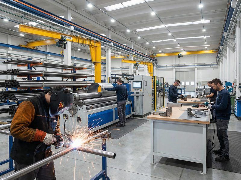
Manufacturing Process
SOLAR TODO used a controlled manufacturing workflow to ensure consistency across both pole types and across the full order quantity. For a project involving thousands of units, process repeatability was just as important as structural design. Standardized fabrication also helped maintain dimensional accuracy, coating quality, and shipping efficiency.
1. Raw Material Preparation
Production began with procurement of Q355B steel plates and sections from qualified mills supported by EN 10204 3.1 mill test certificates. Incoming materials were checked for dimensions, chemistry, and mechanical properties before release to fabrication. This front-end control reduced downstream rework and improved traceability. It also supported batch consistency across the full 7,420-set order.
2. Cutting and Forming
Plates were cut by CNC plasma or flame systems to developed dimensions for pole shafts and attachments. Forming operations produced the required polygonal or circular sections while controlling diameter and straightness tolerances. Tight forming control was especially important for direct-burial poles because embedment performance depends on consistent geometry. Repeatable cutting and forming also improved fit-up speed during high-volume production.
3. Welding
Longitudinal seams and attachment welds were executed in accordance with AWS D1.1. Qualified welding procedures, welder certifications, and inspection hold points were used throughout production. Critical welded areas included bracing nodes, support plates, and accessory connection zones. This level of control reduced the risk of local defects that could affect durability or structural performance.
4. Fit-Up and Assembly
Before galvanizing, components underwent workshop fit-up and dimensional verification. Straightness, squareness, hole alignment, and interface tolerances were checked to reduce field adjustment. Each component was then marked for efficient identification during packing and installation. Accurate pre-assembly also supported smoother logistics and faster site sequencing.
5. Pre-Galvanizing Surface Preparation
Surface preparation included degreasing, pickling, rinsing, and fluxing to remove contaminants and support zinc adhesion. This stage is essential because galvanizing quality depends heavily on surface cleanliness. Consistent preparation also improves coating uniformity at welds, edges, and corners. In corrosive climates, coating continuity is a major factor in long-term service life.
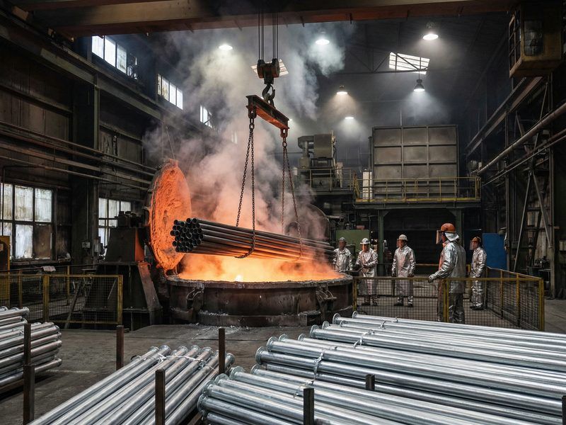
6. Hot-Dip Galvanizing
Fully fabricated steel components were immersed in molten zinc in accordance with ASTM A123. Bath control, immersion time, and drainage practices were managed to achieve the required coating thickness and continuity. According to the International Zinc Association (2022), hot-dip galvanized steel can deliver service life exceeding 50 years in many atmospheric environments. That makes HDG especially suitable for distributed telecom infrastructure with limited maintenance access.
7. Finishing and Packing
After galvanizing, zinc runs and sharp edges were removed and final inspections were completed. Components were bundled and packed to optimize container utilization for shipment from Shanghai. This logistics planning was important because large-volume telecom projects depend on synchronized manufacturing and shipping windows. Well-organized packing also reduced handling damage during overseas transport.
Surface Treatment
Both pole types used Hot-Dip Galvanizing (HDG) as the primary corrosion protection system. For coastal and humid climates, zinc coating remains one of the most practical and proven solutions for outdoor steel structures. It protects not only broad surfaces but also edges, welds, and difficult-to-maintain locations. This is particularly important for telecom routes with many distributed support points.
Hot-Dip Galvanizing (ASTM A123)
- Standard: ASTM A123 – Standard Specification for Zinc (Hot-Dip Galvanized) Coatings on Iron and Steel Products
- Process: Full immersion of fabricated steel in molten zinc, producing metallurgically bonded zinc-iron alloy layers
- Coverage: External and accessible internal surfaces, including welds and edges
Performance in Suriname’s Climate
According to ISO 9223 (2012), coastal tropical environments often fall into corrosivity categories C3 to C4, depending on salinity, humidity, and pollutant levels. In such conditions, HDG provides durable sacrificial protection and reduces maintenance demand compared with uncoated or lightly coated steel. This makes it especially suitable for telecom routes where thousands of poles may be distributed across wide service areas. The coating system also helps reduce lifecycle intervention costs.
IEC guidance for outdoor infrastructure and corrosion-sensitive installations similarly emphasizes the value of durable protective systems in humid and saline environments. IEEE utility structure practice also recognizes corrosion control as a core requirement for long-route reliability and asset life. In practical terms, the zinc layer resists atmospheric attack, protects minor damaged areas by sacrificial action, and reduces the need for on-site repainting. For telecom assets, these lifecycle benefits are often as important as the initial structural design.
- Long-term resistance to humidity and salt-laden air
- Self-protection of minor coating damage through sacrificial action
- Reduced maintenance frequency and lower lifecycle cost
Quality Control
SOLAR TODO integrated quality control throughout procurement, fabrication, galvanizing, and final release. This multi-stage approach was necessary because project success depended on consistency across 7,420 units rather than isolated prototype performance. Robust QC also supports easier field installation, fewer corrections, and better documentation for project engineers. For large repetitive infrastructure, process discipline is a major performance driver.
1. Material Certification
All Q355B steel was supplied with EN 10204 3.1 certification. Random verification of yield strength, tensile strength, elongation, and chemical composition was used to confirm compliance. Material traceability was maintained through the production cycle. This reduced the risk of mixed batches and unsupported substitutions.
2. Dimensional and Fabrication Checks
Inspections covered pole length, straightness, section geometry, and attachment alignment. Tolerances were aligned with accepted steel fabrication practice and relevant structural standards. Early dimensional checks helped prevent cumulative errors during welding and assembly. This was especially important for direct-burial installation, where field adjustment is limited.
3. Welding Quality (AWS D1.1)
All welds were visually inspected to AWS D1.1 acceptance criteria, with NDT applied to critical seams when required. Welding procedure specifications, procedure qualification records, and welder qualifications were documented. This level of control is particularly important for slender support structures where local weld defects can affect fatigue and durability. It also supports traceable quality records for owners and engineers.
4. Galvanizing Quality (ASTM A123)
Coating thickness was measured using magnetic gauges, and continuity checks were carried out to identify bare spots or excessive zinc buildup. Acceptance was based on ASTM A123 minimum coating requirements for structural steel. Consistent galvanizing quality is essential for telecom poles because maintenance access may be limited after installation. Uniform coating performance also improves expected service life in coastal air.
5. Final Inspection
Before shipment, the final inspection verified marking, packing lists, dimensions, and documentation completeness. Random re-checks of critical features were performed to confirm batch consistency. According to OECD (2021), strong quality systems can significantly reduce rework and field issues, reinforcing the value of this integrated inspection regime. Final release control also improved shipment readiness and receiving efficiency.
Production Timeline
Both pole types followed a standardized production schedule that supported synchronized delivery. A repeatable timeline is especially valuable in telecom projects because route construction, logistics, and installation crews must be coordinated closely. SOLAR TODO used parallel production planning to accommodate the larger 6 m pole volume without disrupting the overall shipping program. This helped maintain schedule visibility across design, fabrication, and dispatch.
Standard Production Timeline (Per Product Type)
| Phase | Duration (days) |
|---|---|
| Design | 2 |
| Procurement | 5 |
| Fabrication | 7 |
| Galvanizing | 3 |
| Inspection | 2 |
| Packing | 2 |
| Total | 21 |
- 6 m Poles (6600 sets): 21 days total, supported by parallel production lines
- 12 m Poles (820 sets): 21 days total, aligned with shipment windows from Shanghai
McKinsey (2020) reports that optimized fabrication scheduling can improve steel project delivery times by 15–20%. In this case, a standardized 21-day cycle helped maintain predictability across design, fabrication, galvanizing, and packing. That predictability is critical when supplying large-volume infrastructure to overseas project sites. It also reduces the risk of downstream installation delays.
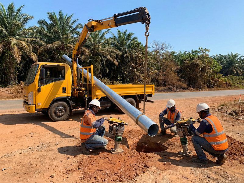
Installation & Erection
The direct-burial concept simplified field erection and reduced dependence on cast-in-place concrete foundations and anchor-bolt templates. For long telecom routes, this can materially shorten installation time and reduce site coordination complexity. Installation quality, however, still depends on accurate excavation, plumb setting, and proper backfill compaction. Field execution therefore remains a key part of structural performance.
1. Site Preparation
Pole locations were surveyed and marked according to the telecom route layout. Underground utility clearance and equipment access were verified before excavation began. Good site preparation reduces delays and lowers the risk of rework during repetitive installation. It also improves crew productivity along long corridor alignments.
2. Foundation Excavation
Holes were drilled or excavated to the specified sizes for each pole type. The 6 m pole required Ø0.4 m × 1 m, while the 12 m pole required Ø0.6 m × 1.8 m. Loose material was removed from the bottom to improve embedment consistency and compaction quality. Accurate excavation dimensions are important for predictable lateral resistance.
3. Pole Placement
Poles were lifted using cranes or truck-mounted lifting equipment with certified slings and handling procedures. Each pole was set vertically and checked for plumb using spirit levels or laser tools. Temporary bracing could be used where needed before final backfilling. Proper handling also helped protect the galvanized surface during erection.
4. Backfilling and Compaction
Backfill was placed in layers and compacted progressively to achieve the required density around the shaft. This step is structurally important because embedment performance depends on soil confinement and stiffness. NREL (2020) and utility pole practice both identify compaction quality as a major determinant of direct-burial behavior. Final grading was shaped to direct surface water away from the pole base area.
5. Cable and Equipment Installation
After the poles were secured, cable brackets, support hardware, and antenna mounts were installed according to design drawings. Cables were then routed and tensioned to maintain required clearances and sag limits. Electrical and signal continuity checks completed the functional installation sequence. This staged approach reduced the risk of misalignment and rework.
6. Final Acceptance
Final acceptance included visual checks for verticality, connection condition, and coating integrity. Installed poles were verified against structural drawings and telecom route requirements, and handover records were compiled. According to field practice cited by telecom infrastructure specialists and IEEE utility guidance, standardized direct-burial systems can reduce installation time substantially compared with custom concrete foundations. The result is faster route completion with lower field complexity.
Pricing Summary
All prices are FOB Shanghai, as stated in quotation TD-2026-0030. Currency and unit pricing are presented exactly as provided in the source data. The pricing structure reflects standardized production and shipping efficiency for high-volume telecom steelwork. It also highlights the economic value of repeatable design and manufacturing.
Product 1: 6 m Cable Support Pole
- Quantity: 6600 sets
- FOB Unit Price: $55.3/ton
- FOB Total Price: $364,980
- Port: Shanghai
Product 2: 12 m Cable Support Pole
- Quantity: 820 sets
- FOB Unit Price: $164/ton
- FOB Total Price: $134,480
- Port: Shanghai
Overall Project Pricing
| Product | Quantity | FOB Unit Price (/ton) | FOB Total Price |
|---|---|---|---|
| 6 m Cable Support Pole | 6600 sets | $55.3 | $364,980 |
| 12 m Cable Support Pole | 820 sets | $164 | $134,480 |
| Grand Total | – | – | $499,460 |
According to ITU (2022), infrastructure remains a major cost component in telecom network expansion, particularly in developing and geographically dispersed markets. Standardized galvanized steel poles help control capex by reducing engineering variation, installation time, and long-term maintenance. This project is a clear example of that value proposition in practice. The combination of durability and repeatability supports better lifecycle economics.
Conclusion
This Paramaribo project shows how SOLAR TODO delivered a large telecom pole package with both engineering rigor and production efficiency. The order included 6600 sets of 6 m poles and 820 sets of 12 m poles, each produced on a 21-day cycle and designed to meet demanding wind, seismic, and corrosion conditions. With verified structural performance, ASTM A123 galvanizing, and direct-burial installation, the system provides a durable and scalable support solution for Suriname’s expanding telecommunications network. The project also demonstrates the value of combining code-based design with industrialized manufacturing.
FAQ
1. How were the wind loads for these poles determined?
Wind loads were calculated using a basic wind speed of 42.5 m/s and Terrain Category D in accordance with ASCE 7-22. The resulting maximum design pressures were 1016.5 Pa for the 6 m pole and 1146.8 Pa for the 12 m pole. These values were then used for member sizing, displacement checks, and foundation evaluation.
2. What are the main differences between the 6 m and 12 m cable support poles?
Both products use Q355B steel and ASTM A123 hot-dip galvanizing, but they differ in height, foundation size, and structural demand. The 6 m pole uses a Ø0.4 m × 1 m direct-burial hole, while the 12 m pole requires Ø0.6 m × 1.8 m. The taller pole also experiences higher wind pressure, larger displacement, and greater seismic base shear.
3. Why was direct burial selected instead of anchor-bolt concrete foundations?
Direct burial reduces field hardware, shortens installation time, and simplifies repetitive construction along a telecom route. For these relatively light steel poles, the specified embedment depths provide the required overturning and lateral resistance when backfill is properly compacted. NREL (2020) identifies direct-embedment systems as a practical solution for many utility and distributed infrastructure applications.
4. How does the galvanizing system support durability in Suriname’s climate?
The poles are protected by hot-dip galvanizing to ASTM A123, which forms a metallurgically bonded zinc coating over the steel surface. In humid and marine-influenced climates, this coating provides both barrier protection and sacrificial protection. According to ISO 9223 and the International Zinc Association, this approach is well suited to corrosive outdoor environments. The result is longer service life and reduced maintenance compared with uncoated steel.
5. Are the poles suitable for future load increases such as added cables or small attachments?
Yes, both products retain structural reserve within the reported utilization ratios. The 6 m pole’s main leg utilization is 0.29, and the 12 m pole’s is 0.63, both below the allowable limit of 1.0. Any future additions should still be checked against the original design envelope before implementation. Engineering review remains necessary for changes in wind area or eccentric loading.
6. What seismic design criteria were applied to these structures?
The design used Ss = 1.28 g and S1 = 0.85 g, resulting in SDS = 1.52 and SD1 = 0.85. Both pole types were classified under Seismic Design Category D. The response coefficient Cs = 0.5067 led to base shears of 0.3 kN for the 6 m pole and 0.9 kN for the 12 m pole.
7. How long did production take for this order?
Each product type followed a 21-day production schedule consisting of design, procurement, fabrication, galvanizing, inspection, and packing. Parallel production lines were used to manage the larger 6 m pole quantity. This allowed SOLAR TODO to maintain both volume output and quality consistency. Standardized scheduling also improved shipment coordination.
8. What quality documentation is available for engineers and project owners?
Documentation includes material certificates to EN 10204, welding records to AWS D1.1, galvanizing records to ASTM A123, and structural design references to ASCE 7-22 and AISC 360-22. These records support inspection, approval, and long-term asset management. They also improve traceability during shipment and installation.
9. Can these pole designs be adapted for other countries or code environments?
Yes, the same basic design platform can be recalculated for different wind speeds, seismic conditions, and local code requirements. Member sizes, embedment depths, and connection details can be adjusted while retaining the overall manufacturing logic. This makes the product family suitable for regional adaptation without starting from scratch. Such flexibility is valuable for multinational telecom programs.
10. How does SOLAR TODO maintain consistency across thousands of poles?
Consistency is achieved through standardized CNC cutting, controlled forming, qualified welding procedures, batch galvanizing, and staged inspections. Sampling and final verification are used to confirm dimensional accuracy, weld quality, and coating thickness. This process discipline is essential when supplying thousands of repetitive structural units. It also reduces field variation during installation.
11. What role does soil compaction play in direct-burial performance?
Soil compaction is critical because it directly affects lateral stiffness, overturning resistance, and long-term pole stability. Even a well-designed embedment depth can underperform if the backfill is loose or unevenly placed. For this reason, backfill should be installed in layers and compacted to the project’s required density. NREL (2020) and utility practice both emphasize this point.
12. Why is Terrain Category D important in the design basis?
Terrain Category D represents open exposure with few obstructions, which generally increases wind effects compared with more sheltered urban terrain. Using this category ensures the poles are checked against a more demanding exposure condition. For coastal and open-route telecom corridors, this is an appropriate and conservative assumption. It improves confidence in serviceability and strength performance.
13. How does IEC and IEEE guidance support this pole design approach?
IEC guidance for outdoor infrastructure emphasizes durable protective systems, environmental suitability, and reliable installation practices in corrosive service conditions. IEEE utility structure guidance similarly highlights load-path continuity, field quality, and long-term reliability for overhead support systems. These principles align closely with the project’s use of galvanized steel, direct burial, and staged quality control. Together, they reinforce the engineering logic behind the selected solution.
14. What makes hot-dip galvanizing preferable to paint for this project?
Hot-dip galvanizing generally offers stronger lifecycle performance for distributed outdoor assets in humid or saline environments. Unlike many paint systems, HDG provides both barrier protection and sacrificial protection, including at edges and weld zones. For a route with thousands of poles, lower maintenance demand can translate into significant operational savings. This is one reason HDG is widely used in telecom and utility infrastructure.
Related Reading
References
- ASCE (2022) – ASCE 7-22: Minimum Design Loads and Associated Criteria for Buildings and Other Structures. American Society of Civil Engineers.
- ICC (2023) – International Building Code 2024 (IBC 2024). International Code Council.
- AISC (2022) – AISC 360-22: Specification for Structural Steel Buildings. American Institute of Steel Construction.
- CEN (2006) – EN 1993-3: Eurocode 3 – Design of steel structures – Towers, masts and chimneys. European Committee for Standardization.
- TIA (2017) – TIA-222-H: Structural Standard for Antenna Supporting Structures and Antennas. Telecommunications Industry Association.
- NREL (2020) – National Renewable Energy Laboratory, reports on pole and foundation design practices for distributed infrastructure.
- ITU (2022) – International Telecommunication Union statistics on global telecom infrastructure and deployment costs.
- International Zinc Association (2022) – Guidance on durability and performance of hot-dip galvanized steel in various atmospheric environments.
- ISO (2012) – ISO 9223: Corrosion of metals and alloys — Corrosivity of atmospheres — Classification, determination and estimation.
- IEC – Relevant guidance for outdoor electrical and infrastructure installations in corrosive environments.
- IEEE – Utility and overhead line structural guidance relevant to pole system load paths, reliability, and field installation practice.
- EPRI (2019) – Electric Power Research Institute publications on pole embedment and structural support practices in wind-exposed regions.
- World Bank (2023) – Telecommunications and mobile subscription indicators for Suriname.
- McKinsey (2020) – Analysis of fabrication scheduling and industrial productivity improvements in steel and infrastructure projects.
- OECD (2021) – Reports on quality systems, rework reduction, and manufacturing performance.