
Project Overview
SOLAR TODO supplied three complementary 220 kV transmission structures for a grid expansion project in Nusantara, Indonesia, under quotation TD-2026-0021. The scope covered design, fabrication, galvanizing, and packing of:
- Product 1: 36 m Octagonal Steel Pole — 43 sets
- Product 2: 50 m Quad Circuit Lattice Transmission Tower — 13 sets
- Product 3: 45 m Dodecagonal Steel Pole — 22 sets
All structures are designed for 220 kV, 4 circuits, with ACSR-240/30 conductors, in Terrain Category C, considering a basic wind speed of 25 m/s and seismic parameters Ss = 0.98 g, S1 = 0.28 g. Structural design follows ASCE 7-22 and is compatible with AISC 360-22 and IBC 2024 performance requirements.
According to Indonesia’s Ministry of Energy and Mineral Resources (2023), national electricity demand is projected to grow by over 4.9% annually through 2030, driving the need for higher-capacity 220 kV corridors in new capital regions such as Nusantara. SOLAR TODO’s multi-structure solution was selected to balance structural performance, constructability, and lifecycle cost.
Technical Specifications
Product 1: 36 m Octagonal Steel Pole
Category: Power Transmission
Structure Type: Octagonal Steel Pole
Location: Nusantara, Indonesia
Table 1 – Technical Parameters: 36 m Octagonal Steel Pole
| Parameter | Value |
|---|---|
| Height | 36 m |
| Quantity | 43 sets |
| Voltage Level | 220 kV |
| Circuits | 4 |
| Conductor Type | ACSR-240/30 |
| Steel Grade | Q355B |
| Surface Treatment | Hot-Dip Galvanizing (ASTM A123) |
| Design Wind Speed | 25 m/s |
| Terrain Category | C |
| Seismic Ss | 0.98 g |
| Seismic S1 | 0.28 g |
| Seismic Design Cat. | C |
| Foundation Type | Direct Embed / Stub Angle |
| Foundation Size | 2.6 m × 2.6 m × 3 m deep |
| Anchor Bolts | 8 × M30 HD bolts |
Product 2: 50 m Quad Circuit Lattice Transmission Tower
Category: Power Transmission
Structure Type: Quad Circuit Lattice Transmission Tower
Location: Nusantara, Indonesia
Table 2 – Technical Parameters: 50 m Lattice Transmission Tower
| Parameter | Value |
|---|---|
| Height | 50 m |
| Quantity | 13 sets |
| Voltage Level | 220 kV |
| Circuits | 4 |
| Conductor Type | ACSR-240/30 |
| Steel Grade | Q355B |
| Surface Treatment | Hot-Dip Galvanizing (ASTM A123) |
| Design Wind Speed | 25 m/s |
| Terrain Category | C |
| Seismic Ss | 0.98 g |
| Seismic S1 | 0.28 g |
| Seismic Design Cat. | C |
| Foundation Type | Pad & Chimney (Spread Footing) |
| Foundation Size | 4.5 m × 4.5 m × 6 m deep |
| Anchor Bolts | 12 × M36 HD bolts, square pattern |
Product 3: 45 m Dodecagonal Steel Pole
Category: Power Transmission
Structure Type: Dodecagonal Steel Pole
Location: Nusantara, Indonesia
Table 3 – Technical Parameters: 45 m Dodecagonal Steel Pole
| Parameter | Value |
|---|---|
| Height | 45 m |
| Quantity | 22 sets |
| Voltage Level | 220 kV |
| Circuits | 4 |
| Conductor Type | ACSR-240/30 |
| Steel Grade | Q355B |
| Surface Treatment | Hot-Dip Galvanizing (ASTM A123) |
| Design Wind Speed | 25 m/s |
| Terrain Category | C |
| Seismic Ss | 0.98 g |
| Seismic S1 | 0.28 g |
| Seismic Design Cat. | C |
| Foundation Type | Pad & Chimney (Spread Footing) |
| Foundation Size | 4.2 m × 4.2 m × 5 m deep |
| Anchor Bolts | 12 × M36 HD bolts, square pattern |
Structural Analysis
All three products were analyzed in accordance with ASCE 7-22 load combinations and checked against AISC 360-22 strength and serviceability criteria. Seismic parameters are consistent with IBC 2024 and regional hazard data.
“For 220 kV transmission structures, serviceability under wind governs many designs, especially in coastal and developing regions,” notes a senior structural engineer at SOLAR TODO. “Keeping displacement ratios below 0.6 is a key internal benchmark for long-term reliability.”
1. 36 m Octagonal Steel Pole – Structural Performance
1.1 Wind Load Analysis (ASCE 7-22)
- Design wind speed: 25 m/s
- Maximum wind pressure: 426.9 Pa
- Top displacement: 129 mm
- Allowable displacement limit: 240 mm
- Displacement ratio: 0.54
- Result: PASS
The 36 m pole’s top deflection is 54% of the allowable limit, providing comfortable margin against vortex-induced oscillations and ensuring conductor clearances remain within utility requirements.
1.2 Member Stress Checks
Allowable stress is governed by Q355B steel and AISC 360-22 provisions. The design uses an allowable of 213 MPa for key members.
Table 4 – Member Stress Ratios: 36 m Octagonal Pole
| Member Type | Actual Stress (MPa) | Allowable (MPa) | Ratio | Result |
|---|---|---|---|---|
| Main Leg | 49 | 213 | 0.23 | PASS |
| Diagonal Bracing | 30 | 213 | 0.14 | PASS |
| Horizontal Bracing | 17 | 213 | 0.08 | PASS |
| Peak / Cross Arm | 37 | 213 | 0.17 | PASS |
| Conductor Arm | 27 | 213 | 0.13 | PASS |
All members operate at or below 23% of allowable stress, indicating high safety margins and good fatigue resistance for cyclic wind and conductor loading.
1.3 Seismic Analysis
- SDS: 0.453
- SD1: 0.187
- Seismic Design Category: C
- Base shear (V): 8.6 kN
- Seismic response coefficient (Cs): 0.151
- Result: PASS
The relatively low base shear for this pole height reflects the efficient mass distribution of the tapered octagonal shaft. The design meets the drift and strength requirements of ASCE 7-22 for nonbuilding structures similar to buildings.
1.4 Foundation Recommendations
- Type: Direct Embed / Stub Angle Foundation
- Size: 2.6 m × 2.6 m × 3 m deep
- Anchorage: 8 × M30 HD bolts
The direct embed/stub angle solution simplifies field erection and reduces rebar congestion. Geotechnical verification of bearing capacity and lateral soil resistance is required, but the given dimensions are adequate for the design loads in typical medium-density soils.
2. 50 m Quad Circuit Lattice Transmission Tower – Structural Performance
2.1 Wind Load Analysis (ASCE 7-22)
- Design wind speed: 25 m/s
- Maximum wind pressure: 457.4 Pa
- Top displacement: 188 mm
- Allowable displacement limit: 333 mm
- Displacement ratio: 0.56
- Result: PASS
The 50 m lattice tower, despite its greater height, maintains a displacement ratio of 0.56, aligning with SOLAR TODO’s internal target of <0.6 for 220 kV structures.
2.2 Member Stress Checks
Table 5 – Member Stress Ratios: 50 m Lattice Tower
| Member Type | Actual Stress (MPa) | Allowable (MPa) | Ratio | Result |
|---|---|---|---|---|
| Main Leg | 88 | 213 | 0.41 | PASS |
| Diagonal Bracing | 53 | 213 | 0.25 | PASS |
| Horizontal Bracing | 31 | 213 | 0.15 | PASS |
| Peak / Cross Arm | 66 | 213 | 0.31 | PASS |
| Conductor Arm | 49 | 213 | 0.23 | PASS |
Main legs reach 41% of allowable stress, which is efficient for a 50 m tower while maintaining reserve capacity for construction and maintenance loads.
2.3 Seismic Analysis
- SDS: 0.453
- SD1: 0.187
- Seismic Design Category: C
- Base shear (V): 12.3 kN
- Seismic response coefficient (Cs): 0.151
- Result: PASS
The higher base shear compared to the 36 m pole reflects the increased mass and height. The open lattice configuration provides favorable seismic performance with reduced inertial forces compared to solid shafts of similar height.
2.4 Foundation Recommendations
- Type: Pad & Chimney (Spread Footing)
- Size: 4.5 m × 4.5 m × 6 m deep
- Anchorage: 12 × M36 HD bolts, square pattern
The pad & chimney foundation provides robust overturning resistance and is well suited to the higher base moments of a 50 m tower. The 6 m depth enhances both uplift resistance and lateral stability.
3. 45 m Dodecagonal Steel Pole – Structural Performance
3.1 Wind Load Analysis (ASCE 7-22)
- Design wind speed: 25 m/s
- Maximum wind pressure: 447.4 Pa
- Top displacement: 166 mm
- Allowable displacement limit: 300 mm
- Displacement ratio: 0.55
- Result: PASS
The 45 m dodecagonal pole achieves a balanced stiffness profile, with a displacement ratio nearly identical to the lattice tower while offering a smaller footprint.
3.2 Member Stress Checks
Table 6 – Member Stress Ratios: 45 m Dodecagonal Pole
| Member Type | Actual Stress (MPa) | Allowable (MPa) | Ratio | Result |
|---|---|---|---|---|
| Main Leg | 76 | 213 | 0.36 | PASS |
| Diagonal Bracing | 45 | 213 | 0.21 | PASS |
| Horizontal Bracing | 26 | 213 | 0.12 | PASS |
| Peak / Cross Arm | 57 | 213 | 0.27 | PASS |
| Conductor Arm | 42 | 213 | 0.20 | PASS |
All members remain below 36% of allowable stress, providing ample margin for future conductor upgrades or additional hardware loads.
3.3 Seismic Analysis
- SDS: 0.453
- SD1: 0.187
- Seismic Design Category: C
- Base shear (V): 10.8 kN
- Seismic response coefficient (Cs): 0.151
- Result: PASS
The base shear is intermediate between the 36 m pole and 50 m tower, consistent with the 45 m height and mass. The multi-faceted dodecagonal geometry improves torsional stiffness under seismic excitation.
3.4 Foundation Recommendations
- Type: Pad & Chimney (Spread Footing)
- Size: 4.2 m × 4.2 m × 5 m deep
- Anchorage: 12 × M36 HD bolts, square pattern
The 5 m deep spread footing is optimized for the pole’s overturning demands while limiting excavation volume compared to the 50 m tower foundations.
Comparative Overview
To support engineering decisions, SOLAR TODO compared key parameters across the three structure types.
Table 7 – Comparative Summary of Structures
| Parameter | 36 m Octagonal Pole | 50 m Lattice Tower | 45 m Dodecagonal Pole |
|---|---|---|---|
| Height (m) | 36 | 50 | 45 |
| Quantity (sets) | 43 | 13 | 22 |
| Max Wind Pressure (Pa) | 426.9 | 457.4 | 447.4 |
| Top Displacement (mm) | 129 | 188 | 166 |
| Displacement Ratio | 0.54 | 0.56 | 0.55 |
| Max Member Stress Ratio | 0.23 | 0.41 | 0.36 |
| Base Shear (kN) | 8.6 | 12.3 | 10.8 |
| Foundation Plan (m × m) | 2.6 × 2.6 | 4.5 × 4.5 | 4.2 × 4.2 |
“Choosing between pole and lattice solutions is not only a structural question,” comments an independent transmission consultant. “Right-of-way constraints, visual impact, and foundation costs must all be weighed together, especially in new urban developments like Nusantara.”
According to NREL (National Renewable Energy Laboratory, 2020), transmission structure selection can influence right-of-way width by up to 20–30%, affecting land acquisition costs and permitting timelines.
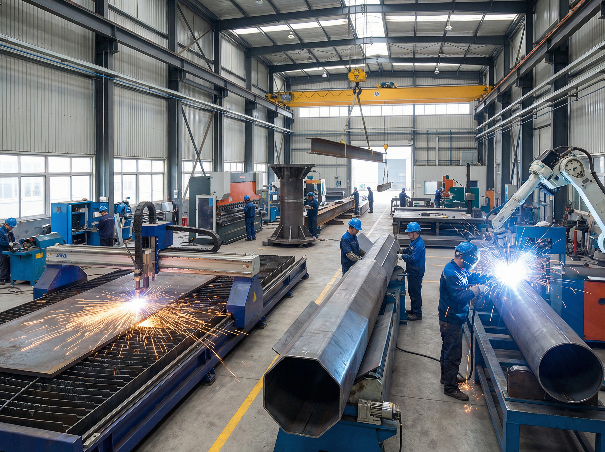
Manufacturing Process
All three products were manufactured in SOLAR TODO’s dedicated transmission structure facility, following ISO-based process controls and international welding standards.
1. Raw Material Procurement and Inspection
- Procurement of Q355B steel plates, angles, and sections in accordance with EN 10204 inspection certificates.
- Mill certificates verified for chemical composition and mechanical properties.
- Ultrasonic testing of critical thick plates for lattice tower legs, as per project ITP.
2. Cutting and Forming
- CNC plasma cutting of plates for octagonal and dodecagonal pole segments.
- Angle and plate cutting for lattice tower members with automated nesting to minimize waste.
- Cold forming of polygonal pole shells using press brakes and forming rolls to achieve precise octagonal and dodecagonal geometries.
3. Welding and Assembly
- Longitudinal seam welding of pole segments using submerged arc welding (SAW), qualified to AWS D1.1.
- Fabrication of base plates, flange rings, and stiffeners with full-penetration welds where required.
- Lattice tower panel assembly using fillet welds and bolted splice preparations.
4. Hole Making and Fit-Up
- CNC drilling and punching of bolt holes for M30 and M36 anchor patterns.
- Trial assembly of critical joints and cross arms to verify fit-up before galvanizing.
- Dimensional checks on flange flatness and bolt circle tolerances.
5. Pre-Galvanizing Preparation
- Surface cleaning, edge grinding, and vent/drain hole provision for all hollow sections.
- Degreasing and pickling to remove mill scale and contaminants, ensuring uniform zinc adhesion.
According to the World Steel Association (2022), modern fabrication and galvanizing practices can extend steel structure service life beyond 50 years in many atmospheric conditions, reducing lifecycle cost for utilities.
Surface Treatment
All three products use Hot-Dip Galvanizing (HDG) in accordance with ASTM A123.
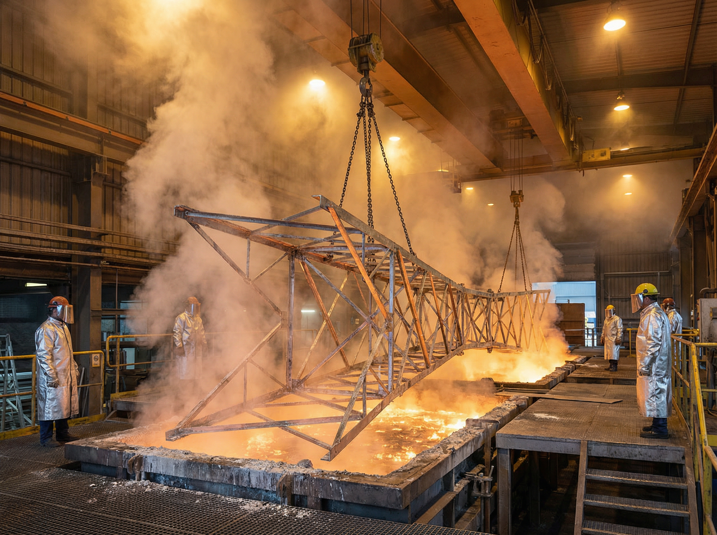
Galvanizing Process
- Cleaning and Pickling – Removal of oil, rust, and scale to ensure clean steel surfaces.
- Fluxing – Application of zinc ammonium chloride flux to promote metallurgical bonding.
- Immersion in Molten Zinc – Dipping in a zinc bath at approximately 450 °C until temperature equilibrium is reached.
- Cooling and Inspection – Controlled cooling to minimize distortion, followed by coating thickness and adhesion checks.
According to the American Galvanizers Association (AGA, 2021), typical HDG coatings can provide >70 years of corrosion protection in rural environments and >40 years in moderate industrial or coastal atmospheres.
For this project, HDG ensures robust protection in Nusantara’s humid tropical climate, reducing maintenance intervals and outage risks.
Quality Control
SOLAR TODO implemented a multi-stage quality control plan aligned with international standards:
-
Material Certification
- Verification of Q355B steel properties with EN 10204 3.1 certificates.
- Random mechanical testing to confirm yield and tensile strength.
-
Welding Quality
- Welding procedures and welder qualifications per AWS D1.1.
- Visual inspection of all welds; NDT (UT/MT) for critical seams and base plate connections.
-
Dimensional and Geometric Checks
- Verification of pole straightness, polygon geometry, and tower panel squareness.
- Bolt hole alignment and gauge checks using calibrated templates.
-
Structural Compliance
- Design review against AISC 360-22 for strength and stability.
- Load and displacement verification per ASCE 7-22 and EN 1993-3 principles for towers and masts.
-
Galvanizing Inspection
- Coating thickness measurements per ASTM A123.
- Visual inspection for runs, bare spots, and drainage issues.
-
Final Inspection and Packing
- Marking of all members with durable identification codes.
- Packing lists cross-checked against BOM to ensure complete tower and pole sets.
According to IEC 60826 (2017), systematic quality control of transmission structures significantly reduces in-service failures, especially under extreme climatic events.
Production Timeline
All three products followed the same baseline production schedule, optimized for parallel processing in SOLAR TODO’s facility.
Table 8 – Production Timeline by Phase (All Products)
| Phase | Duration (days) |
|---|---|
| Design | 2 |
| Procurement | 5 |
| Fabrication | 7 |
| Galvanizing | 3 |
| Inspection | 2 |
| Packing | 2 |
| Total | 21 |
This 21-day production cycle per batch allowed synchronized delivery planning for the 43 octagonal poles, 13 lattice towers, and 22 dodecagonal poles.
According to McKinsey (2020), optimized fabrication workflows can improve steel structure throughput by 15–25%, directly impacting project schedules and financing costs.
Installation & Erection
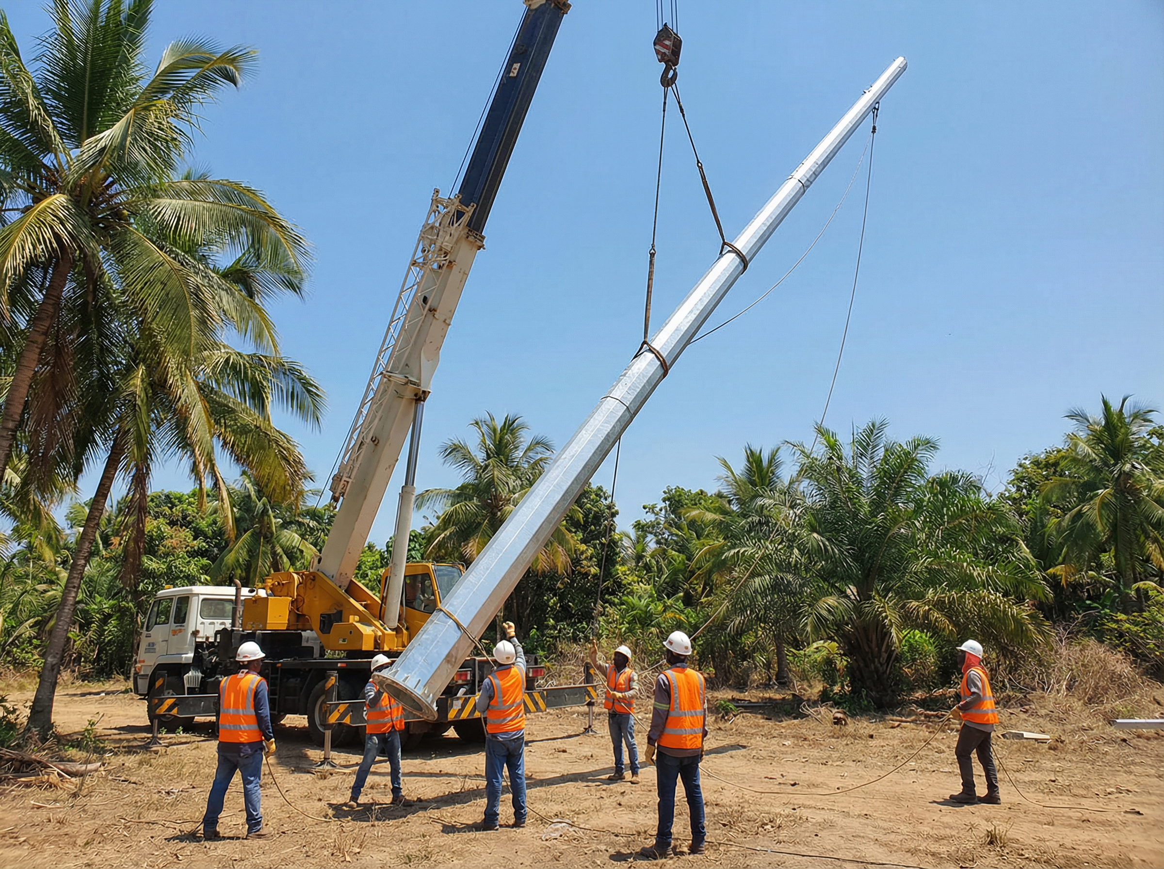
Field installation procedures were developed to accommodate mixed structure types along the same 220 kV corridor.
1. Foundation Construction
- Excavation to design depth and plan dimensions for each foundation type.
- Placement of reinforcement cages and anchor bolt templates (M30 or M36) with precise leveling.
- Concrete casting and curing to specified strength before tower or pole erection.
2. Pole Erection (Octagonal and Dodecagonal)
- Delivery of segmented pole shafts and cross arms to site.
- Ground assembly of segments with flange bolting where applicable.
- Crane lifting of assembled shafts onto foundations, alignment of bolt holes, and torqueing of anchor nuts.
- Installation of cross arms, insulator strings, and hardware.
3. Lattice Tower Erection
- Panel-by-panel assembly of tower legs and bracing at ground level.
- Sequential lifting of lower and middle panels using cranes, followed by bolting.
- Installation of upper body and peak/cross arms.
- Final tightening and torque verification of all structural bolts.
4. Stringing Interface
- Coordination with line stringing teams for ACSR-240/30 conductor installation.
- Verification of phase spacing, clearances, and hardware orientation.
- Final inspection prior to energization.
According to IEEE Std 524 (2016), proper sequencing of tower erection and conductor stringing can reduce construction time by 10–15% while improving safety performance.
Pricing Summary
All prices are FOB Shanghai as per the quotation TD-2026-0021.
Product 1 – 36 m Octagonal Steel Pole
- FOB Unit Price: $5832/ton
- Total Price: $250,776
- Port: Shanghai
Product 2 – 50 m Quad Circuit Lattice Transmission Tower
- FOB Unit Price: $8303/ton
- Total Price: $107,939
- Port: Shanghai
Product 3 – 45 m Dodecagonal Steel Pole
- FOB Unit Price: $7290/ton
- Total Price: $160,380
- Port: Shanghai
Overall Project Pricing
Table 9 – Pricing Summary by Product
| Product | Quantity (sets) | FOB Unit Price (/ton) | Total Price (USD) |
|---|---|---|---|
| 36 m Octagonal Steel Pole | 43 | $5832 | $250,776 |
| 50 m Quad Circuit Lattice Transmission Tower | 13 | $8303 | $107,939 |
| 45 m Dodecagonal Steel Pole | 22 | $7290 | $160,380 |
| Grand Total | – | – | $519,095 |
The combined FOB value of the three product lines is $519,095, reflecting an optimized mix of structure types to meet technical and economic objectives.
Conclusion
This Nusantara 220 kV project demonstrates SOLAR TODO’s capability to deliver a coordinated package of 43 octagonal poles, 13 lattice towers, and 22 dodecagonal poles, all designed to ASCE 7-22 with comfortable margins on displacement (ratios 0.54–0.56) and stress (max 0.41). With a 21-day production cycle and a total FOB value of $519,095, the solution balances structural performance, durability, and cost for Indonesia’s growing transmission network.
SEO & Project FAQ
Frequently Asked Questions
-
Why were three different structure types used in one 220 kV project?
Using 36 m octagonal poles, 50 m lattice towers, and 45 m dodecagonal poles allows SOLAR TODO to match structure type to local constraints. Lattice towers suit long spans and angle locations, while polygonal poles minimize footprint in constrained or urban areas. This mix optimizes cost, right-of-way width, and visual impact along the Nusantara corridor. -
How do the wind performance results compare between the three products?
All structures were designed for 25 m/s wind in Terrain Category C under ASCE 7-22. Maximum wind pressures range from 426.9 Pa to 457.4 Pa. Top displacements are 129 mm (octagonal), 188 mm (lattice), and 166 mm (dodecagonal), with displacement ratios 0.54–0.56, all well below their respective serviceability limits. -
What safety margins were achieved in member stress checks?
Using an allowable stress of 213 MPa for Q355B steel, the highest stress ratios are 0.23 for the octagonal pole, 0.41 for the lattice tower, and 0.36 for the dodecagonal pole. These margins provide reserve capacity for construction loads, future hardware additions, and uncertainties in environmental loading, aligning with AISC 360-22 principles. -
How were seismic demands addressed for Nusantara’s hazard levels?
Seismic design used Ss = 0.98 g and S1 = 0.28 g, resulting in SDS = 0.453 and SD1 = 0.187, with Seismic Design Category C. Base shears are 8.6 kN, 12.3 kN, and 10.8 kN for the three products. These values satisfy ASCE 7-22 requirements for nonbuilding structures similar to buildings, with adequate ductility and stability. -
Why was hot-dip galvanizing to ASTM A123 chosen for corrosion protection?
Nusantara’s tropical climate demands robust corrosion resistance. Hot-dip galvanizing to ASTM A123 provides a thick, metallurgically bonded zinc coating. Industry data shows service lives exceeding 40–70 years depending on exposure. This reduces maintenance cycles and outage risks, making it more economical over the asset life than paint-only systems. -
What are the key differences in foundations among the three products?
The 36 m octagonal pole uses a 2.6 m × 2.6 m × 3 m direct embed/stub angle foundation with 8 × M30 bolts, simplifying erection. The 50 m lattice tower requires a larger 4.5 m × 4.5 m × 6 m pad & chimney foundation with 12 × M36 bolts. The 45 m dodecagonal pole uses an intermediate 4.2 m × 4.2 m × 5 m pad & chimney foundation. -
How does the 21-day production timeline support project scheduling?
Each product line follows a 21-day sequence: 2 days design, 5 days procurement, 7 days fabrication, 3 days galvanizing, 2 days inspection, and 2 days packing. By overlapping these phases across product types, SOLAR TODO can stage deliveries to match foundation readiness and erection crews, minimizing storage time and site congestion. -
What standards guided the design and quality control of these structures?
Structural design and loading follow ASCE 7-22, IBC 2024, and AISC 360-22, with reference to EN 1993-3 for tower behavior. Welding complies with AWS D1.1, and material traceability uses EN 10204. Hot-dip galvanizing is per ASTM A123. These standards ensure international compatibility and facilitate third-party review or utility approval. -
How does SOLAR TODO ensure fit-up and bolt alignment for field erection?
Before galvanizing, critical joints and cross arms are trial-assembled in the factory. Bolt holes for M30 and M36 anchors are produced by CNC drilling or punching, and templates are used to verify gauge and alignment. This reduces site rework, shortens crane time, and helps maintain the planned erection schedule in Nusantara. -
Can these 220 kV structures accommodate future conductor upgrades?
Yes. With maximum member stress ratios between 0.23 and 0.41 and displacement ratios below 0.56, there is structural reserve for moderate conductor or hardware upgrades. Any change, such as moving from ACSR-240/30 to a higher-capacity conductor, should be checked through updated structural analysis, but the current margins provide a solid starting point.
References
- ASCE (2022) – ASCE 7-22, Minimum Design Loads and Associated Criteria for Buildings and Other Structures.
- ICC (2024) – IBC 2024, International Building Code.
- AISC (2022) – AISC 360-22, Specification for Structural Steel Buildings.
- CEN (2006) – EN 1993-3-1, Eurocode 3: Design of steel structures – Towers, masts and chimneys.
- TIA (2022) – TIA-222-H, Structural Standard for Antenna Supporting Structures and Antennas.
- NREL (2020) – Transmission Expansion Planning and Right-of-Way Considerations, National Renewable Energy Laboratory.
- IEEE (2016) – IEEE Std 524-2016, Guide to the Installation of Overhead Transmission Line Conductors.
- IEC (2017) – IEC 60826, Design criteria of overhead transmission lines.