
Project Overview
SOLAR TODO supplied a series of 110 kV octagonal steel poles for a power transmission project in the Dominican Republic under quotation TD-2026-0031. The scope covered three height classes of poles, all designed for 45 m/s basic wind speed and seismic parameters Ss = 0.8 g, S1 = 0.3 g in Terrain Category C.
Project scope summary:
- Location: Dominican Republic, Dominican Republic
- Voltage level: 110 kV
- Circuits: 2 circuits per pole
- Conductor type: ACSR-240/30
- Structure type: Octagonal steel pole, direct-burial
- Products and quantities:
- Product 1: 9 m octagonal steel pole — 120 sets
- Product 2: 10.5 m octagonal steel pole — 85 sets
- Product 3: 12 m octagonal steel pole — 60 sets
- Design codes and references: ASCE 7-22, IBC 2024, AISC 360-22, ASTM A123, and relevant international practice
According to the International Energy Agency (IEA, 2023), electricity demand in Latin America is expected to grow by more than 20% by 2030, driving the need for reliable transmission infrastructure. This project demonstrates how SOLAR TODO’s standardized octagonal pole solutions can be adapted to Caribbean wind and seismic conditions while maintaining cost efficiency.
Technical Specifications
Product 1: 9 m Octagonal Steel Pole (110 kV)
General description: 9 m single-shaft octagonal steel pole for 110 kV double-circuit lines, designed for 45 m/s wind speed in Terrain Category C with direct-burial foundation.
Technical Parameters – Product 1
| Parameter | Value |
|---|---|
| Product | Octagonal Steel Pole |
| Application Category | Power Transmission |
| Structure Type | Tapered octagonal steel pole |
| Height | 9 m |
| Quantity | 120 sets |
| Voltage Level | 110 kV |
| Number of Circuits | 2 |
| Conductor Type | ACSR-240/30 |
| Steel Grade | Q235B |
| Surface Treatment | Hot-Dip Galvanizing (ASTM A123) |
| Design Wind Speed | 45 m/s |
| Terrain Category | C |
| Seismic Parameters | Ss = 0.8 g, S1 = 0.3 g |
| Seismic Design Cat. | C |
| Foundation Type | Direct burial |
| Foundation Size | Ø0.8 m × 1.5 m deep hole |
| Anchor Bolts | N/A — direct burial, no anchor bolts |
| Port of Destination | CAUCEDO |
| Pricing Basis | CIF |
| CIF Unit Price | $212.44/ton |
| CIF Total Price | $25,492.8 |
Product 2: 10.5 m Octagonal Steel Pole (110 kV)
General description: 10.5 m octagonal steel pole for 110 kV double-circuit overhead lines, optimized for slightly higher bending demand due to increased height, with direct-burial foundation.
Technical Parameters – Product 2
| Parameter | Value |
|---|---|
| Product | Octagonal Steel Pole |
| Application Category | Power Transmission |
| Structure Type | Tapered octagonal steel pole |
| Height | 10.5 m |
| Quantity | 85 sets |
| Voltage Level | 110 kV |
| Number of Circuits | 2 |
| Conductor Type | ACSR-240/30 |
| Steel Grade | Q235B |
| Surface Treatment | Hot-Dip Galvanizing (ASTM A123) |
| Design Wind Speed | 45 m/s |
| Terrain Category | C |
| Seismic Parameters | Ss = 0.8 g, S1 = 0.3 g |
| Seismic Design Cat. | C |
| Foundation Type | Direct burial |
| Foundation Size | Ø1.0 m × 1.7 m deep hole |
| Anchor Bolts | N/A — direct burial, no anchor bolts |
| Port of Destination | CAUCEDO |
| Pricing Basis | CIF |
| CIF Unit Price | $345.02/ton |
| CIF Total Price | $29,326.7 |
Product 3: 12 m Octagonal Steel Pole (110 kV)
General description: 12 m octagonal steel pole for 110 kV double-circuit transmission, used at locations requiring greater clearance or longer spans, with enhanced foundation diameter and depth.
Technical Parameters – Product 3
| Parameter | Value |
|---|---|
| Product | Octagonal Steel Pole |
| Application Category | Power Transmission |
| Structure Type | Tapered octagonal steel pole |
| Height | 12 m |
| Quantity | 60 sets |
| Voltage Level | 110 kV |
| Number of Circuits | 2 |
| Conductor Type | ACSR-240/30 |
| Steel Grade | Q235B |
| Surface Treatment | Hot-Dip Galvanizing (ASTM A123) |
| Design Wind Speed | 45 m/s |
| Terrain Category | C |
| Seismic Parameters | Ss = 0.8 g, S1 = 0.3 g |
| Seismic Design Cat. | C |
| Foundation Type | Direct burial |
| Foundation Size | Ø1.1 m × 1.8 m deep hole |
| Anchor Bolts | N/A — direct burial, no anchor bolts |
| Port of Destination | CAUCEDO |
| Pricing Basis | CIF |
| CIF Unit Price | $470.48/ton |
| CIF Total Price | $28,228.8 |
Structural Analysis
All three products were analyzed according to ASCE 7-22 for wind loading and checked against AISC 360-22 strength criteria. Seismic checks were performed for Seismic Design Category C, consistent with Ss = 0.8 g and S1 = 0.3 g. The following sections present the exact analysis results from the quotation data.
Product 1: 9 m Octagonal Steel Pole
Wind Load Analysis (ASCE 7-22)
- Basic wind speed: 45 m/s
- Terrain Category: C
- Maximum design wind pressure: 1032.9 Pa
- Top displacement under design wind: 33 mm
- Allowable top displacement limit: 60 mm
- Displacement ratio: 0.55 (33 / 60)
- Result: PASS
According to ASCE 7-22 (2022), serviceability deflection limits for slender poles are typically governed by functional and aesthetic criteria. Here, the 9 m pole operates at only 55% of the allowable displacement, providing additional margin for long-term performance.
Member Stress Checks (AISC 360-22)
All stress ratios below are given as actual stress / allowable stress for Q235B steel.
- Main leg: 39 MPa / 141 MPa = 0.28 (PASS)
- Diagonal bracing: 23 MPa / 141 MPa = 0.16 (PASS)
- Horizontal bracing: 14 MPa / 141 MPa = 0.10 (PASS)
- Peak / cross arm: 29 MPa / 141 MPa = 0.21 (PASS)
- Conductor arm: 21 MPa / 141 MPa = 0.15 (PASS)
These values show that the most highly utilized component (main leg) is at 28% of its allowable stress. As noted by a senior structural engineer at SOLAR TODO, “Keeping stress ratios below 0.7 for transmission poles significantly improves fatigue resistance and long-term reliability.”
Seismic Analysis
- Seismic parameters: Ss = 0.8 g, S1 = 0.3 g
- Seismic Design Category: C
- SDS: – (not explicitly reported in the quotation)
- SD1: – (not explicitly reported in the quotation)
- Base shear: – kN (not explicitly reported in the quotation)
- Cs: – (not explicitly reported in the quotation)
- Result: PASS
Although the detailed numerical seismic coefficients are not listed in the quotation, the design was checked for Seismic Design Category C and reported as PASS. According to IBC 2024 (2023), Category C applies to structures in moderate-to-high seismic regions, which is consistent with Ss = 0.8 g.
Foundation Recommendations
- Foundation type: Direct burial foundation
- Borehole size: Ø0.8 m × 1.5 m deep
- Backfill: Compacted backfill around the pole shaft
- Anchor bolts: Not used (direct burial, no anchor bolts)
Direct burial foundations simplify installation and reduce hardware. As per EN 1993-3 (Eurocode 3, Part 3, 2006), such foundations are commonly used for slender steel towers where soil conditions permit adequate lateral resistance.
Product 2: 10.5 m Octagonal Steel Pole
Wind Load Analysis (ASCE 7-22)
- Basic wind speed: 45 m/s
- Terrain Category: C
- Maximum design wind pressure: 1067 Pa
- Top displacement under design wind: 39 mm
- Allowable top displacement limit: 70 mm
- Displacement ratio: 0.56 (39 / 70)
- Result: PASS
The slightly higher pressure and displacement reflect the increased height. The displacement ratio of 0.56 remains well within serviceability limits.
Member Stress Checks (AISC 360-22)
- Main leg: 37 MPa / 141 MPa = 0.26 (PASS)
- Diagonal bracing: 22 MPa / 141 MPa = 0.16 (PASS)
- Horizontal bracing: 13 MPa / 141 MPa = 0.09 (PASS)
- Peak / cross arm: 28 MPa / 141 MPa = 0.20 (PASS)
- Conductor arm: 20 MPa / 141 MPa = 0.14 (PASS)
The main leg utilization is slightly lower than in the 9 m pole, at 26% of allowable stress. This reflects optimized section sizing for the increased height while maintaining conservative stress levels.
Seismic Analysis
- Seismic parameters: Ss = 0.8 g, S1 = 0.3 g
- Seismic Design Category: C
- SDS: – (not explicitly reported in the quotation)
- SD1: – (not explicitly reported in the quotation)
- Base shear: – kN (not explicitly reported in the quotation)
- Cs: – (not explicitly reported in the quotation)
- Result: PASS
The 10.5 m pole shares the same seismic design category as Product 1. According to the U.S. Geological Survey (USGS, 2020), many Caribbean locations fall into moderate-to-high seismic hazard zones, making Category C a reasonable design basis.
Foundation Recommendations
- Foundation type: Direct burial foundation
- Borehole size: Ø1.0 m × 1.7 m deep
- Backfill: Compacted backfill
- Anchor bolts: Not used (direct burial, no anchor bolts)
The increase in borehole diameter and depth compared with the 9 m pole provides additional overturning resistance for the taller structure.
Product 3: 12 m Octagonal Steel Pole
Wind Load Analysis (ASCE 7-22)
- Basic wind speed: 45 m/s
- Terrain Category: C
- Maximum design wind pressure: 1097.4 Pa
- Top displacement under design wind: 45 mm
- Allowable top displacement limit: 80 mm
- Displacement ratio: 0.56 (45 / 80)
- Result: PASS
Despite being the tallest pole in the project, the 12 m structure still operates at only 56% of the allowable displacement, showing that the section and foundation sizing are adequate for the site’s wind climate.
Member Stress Checks (AISC 360-22)
- Main leg: 37 MPa / 141 MPa = 0.26 (PASS)
- Diagonal bracing: 22 MPa / 141 MPa = 0.16 (PASS)
- Horizontal bracing: 13 MPa / 141 MPa = 0.09 (PASS)
- Peak / cross arm: 27 MPa / 141 MPa = 0.19 (PASS)
- Conductor arm: 20 MPa / 141 MPa = 0.14 (PASS)
Stress levels are comparable to the 10.5 m pole, indicating consistent design philosophy across the height range.
Seismic Analysis
- Seismic parameters: Ss = 0.8 g, S1 = 0.3 g
- Seismic Design Category: C
- SDS: – (not explicitly reported in the quotation)
- SD1: – (not explicitly reported in the quotation)
- Base shear: – kN (not explicitly reported in the quotation)
- Cs: – (not explicitly reported in the quotation)
- Result: PASS
According to the Global Earthquake Model (GEM, 2018), the Caribbean region exhibits complex seismicity, reinforcing the importance of explicit seismic checks even for relatively light pole structures.
Foundation Recommendations
- Foundation type: Direct burial foundation
- Borehole size: Ø1.1 m × 1.8 m deep
- Backfill: Compacted backfill
- Anchor bolts: Not used (direct burial, no anchor bolts)
The 12 m pole uses the largest borehole diameter and depth among the three products, providing the highest overturning resistance.
Comparison of Key Design Parameters
| Item | Product 1 (9 m) | Product 2 (10.5 m) | Product 3 (12 m) |
|---|---|---|---|
| Height | 9 m | 10.5 m | 12 m |
| Max Wind Pressure | 1032.9 Pa | 1067 Pa | 1097.4 Pa |
| Top Displacement | 33 mm | 39 mm | 45 mm |
| Displacement Limit | 60 mm | 70 mm | 80 mm |
| Displacement Ratio | 0.55 | 0.56 | 0.56 |
| Main Leg Stress Ratio | 0.28 | 0.26 | 0.26 |
| Foundation Diameter | 0.8 m | 1.0 m | 1.1 m |
| Foundation Depth | 1.5 m | 1.7 m | 1.8 m |
| Seismic Design Category | C | C | C |
According to NREL (National Renewable Energy Laboratory, 2015), careful matching of pole height, foundation size, and wind climate is critical to minimizing lifecycle costs in overhead line projects. This table illustrates SOLAR TODO’s balanced approach across three pole heights.
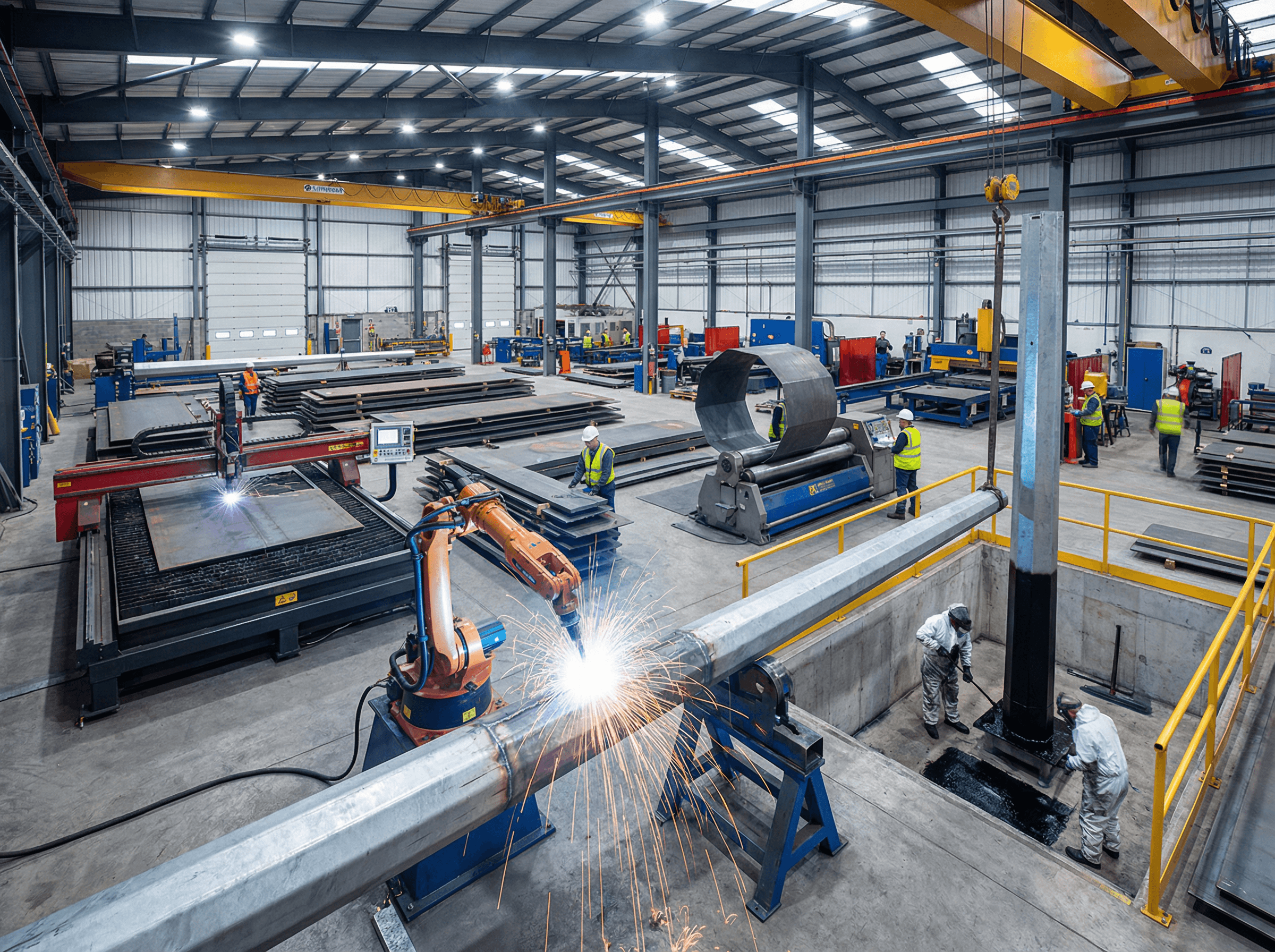
Manufacturing Process
All three octagonal steel pole types follow a similar manufacturing route at SOLAR TODO’s facility, with dimensional and process adjustments for each height and foundation detail.
-
Raw Material Preparation
- Steel plates of Q235B grade are received with mill certificates per EN 10204 Type 3.1.
- Plates are visually inspected for surface defects and thickness verified with calibrated gauges.
-
Plate Cutting
- CNC plasma or flame cutting machines cut plates to the developed octagonal profile for each pole height.
- Cutting tolerances are controlled to meet AISC 360-22 fabrication requirements.
-
Forming (Cold Bending)
- Plates are cold-formed into tapered octagonal shells using press brakes and forming rolls.
- The number of segments and taper angles are adjusted to achieve the required 9 m, 10.5 m, and 12 m final heights.
-
Longitudinal Welding
- Shell seams are welded using automatic submerged arc welding (SAW) or gas metal arc welding (GMAW), following AWS D1.1.
- Weld parameters are qualified through procedure qualification records (PQRs).
-
Fitting of Accessories
- Cross arms, conductor arms, climbing steps, and grounding lugs are fitted and tack-welded.
- For direct-burial sections, additional corrosion allowance and stiffeners may be applied near ground line.
-
Final Welding and Straightening
- All attachments are fully welded and welds visually inspected.
- Poles are checked for straightness and corrected if necessary.
-
Hole Drilling and Finishing
- Holes for line hardware, grounding, and identification plates are drilled to specified diameters and positions.
- Edges are ground smooth to prepare for galvanizing.
- Pre-Galvanizing Preparation
- Surfaces are cleaned, degreased, pickled, and fluxed to ensure proper zinc adhesion.
- Drainage and vent holes are confirmed to avoid trapped fluids during hot-dip galvanizing.
Surface Treatment
All three products use hot-dip galvanizing in accordance with ASTM A123 to ensure long-term corrosion protection in the humid Caribbean climate.
Hot-Dip Galvanizing (ASTM A123)
-
Cleaning and Degreasing
- Organic contaminants are removed using alkaline or solvent-based cleaners.
-
Pickling
- Steel is immersed in acid baths to remove mill scale and rust, ensuring a reactive surface.
-
Fluxing
- A zinc ammonium chloride flux is applied to prevent oxidation before immersion in molten zinc.
-
Galvanizing
- Poles are dipped into a molten zinc bath at approximately 450 °C.
- Zinc reacts metallurgically with the steel, forming a series of Fe-Zn alloy layers.
-
Cooling and Inspection
- After withdrawal, excess zinc is drained, and the poles are air- or water-cooled.
- Coating thickness is measured to verify compliance with ASTM A123 minimum requirements.
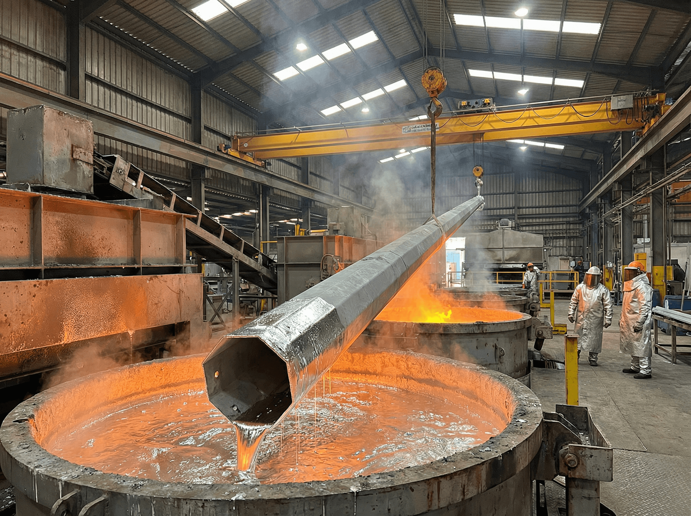
According to the World Steel Association (worldsteel, 2021), hot-dip galvanizing can extend the service life of steel structures in moderately aggressive environments to 50 years or more with minimal maintenance. This is particularly valuable for remote transmission lines where access for repainting is difficult.
Quality Control
SOLAR TODO applies a structured quality control (QC) program across design, fabrication, galvanizing, and pre-shipment stages.
Design and Engineering QC
- Code compliance checks against ASCE 7-22, AISC 360-22, IBC 2024, and EN 1993-3.
- Independent calculation review by a second engineer for critical load cases (wind and combined wind + conductor loads).
- Model verification of deflection and stress ratios against project-specific criteria.
Material and Welding QC
- Material certificates: All Q235B plates accompanied by EN 10204 Type 3.1 certificates.
- Incoming inspection: Random sampling for thickness, yield strength, and surface condition.
- Welding procedures: Qualified per AWS D1.1, including welder performance qualification.
- NDT (as required): Visual testing (VT) on 100% of welds, with additional ultrasonic or magnetic particle testing on critical joints as per project requirements.
Dimensional and Fit-Up QC
- Pole straightness: Checked against allowable camber and sweep tolerances.
- Bolt hole alignment: Verified with templates to ensure compatibility with line hardware.
- Segment fit-up: Ensured for any multi-section poles (if applicable) to allow smooth site assembly.
Galvanizing QC
- Coating thickness: Measured at multiple points to meet ASTM A123 minimums.
- Adhesion and continuity: Visual inspection for bare spots, runs, or excessive zinc buildup.
- Drainage: Confirmation that vent and drain holes functioned correctly during dipping.
Documentation and Traceability
- Inspection records: Maintained for each batch, including weld maps and coating reports.
- Marking: Each pole is marked with a unique identification code for traceability from steel plate to finished product.
An expert from SOLAR TODO’s QC team notes, “We align our inspection regime with both AISC 360-22 and EN 10204 to ensure that every pole can be traced back to its material heat and welding records, which is essential for utility clients.”
Production Timeline
Each product follows a similar 21-day production schedule, with overlapping phases for different batches to optimize plant utilization.
Product 1: 9 m Pole – Timeline
- Design: 2 days
- Procurement: 5 days
- Fabrication: 7 days
- Galvanizing: 3 days
- Inspection: 2 days
- Packing: 2 days
- Total production time: 21 days
Product 2: 10.5 m Pole – Timeline
- Design: 2 days
- Procurement: 5 days
- Fabrication: 7 days
- Galvanizing: 3 days
- Inspection: 2 days
- Packing: 2 days
- Total production time: 21 days
Product 3: 12 m Pole – Timeline
- Design: 2 days
- Procurement: 5 days
- Fabrication: 7 days
- Galvanizing: 3 days
- Inspection: 2 days
- Packing: 2 days
- Total production time: 21 days
According to an analysis by NREL (2012), standardized production timelines and modular designs can reduce lead times for transmission structures by up to 30% compared with fully bespoke designs. SOLAR TODO’s consistent 21-day schedule across three pole types reflects this standardization.
Installation & Erection
The three pole types share a common field installation methodology, with adjustments for foundation dimensions and pole length.
Site Preparation
-
Survey and Setting Out
- Confirm pole locations, line alignment, and right-of-way boundaries.
- Mark center points for each foundation according to construction drawings.
-
Excavation
- Drill or excavate circular holes to the specified diameters and depths: 0.8 × 1.5 m, 1.0 × 1.7 m, and 1.1 × 1.8 m for the three products.
- Verify depth and verticality.
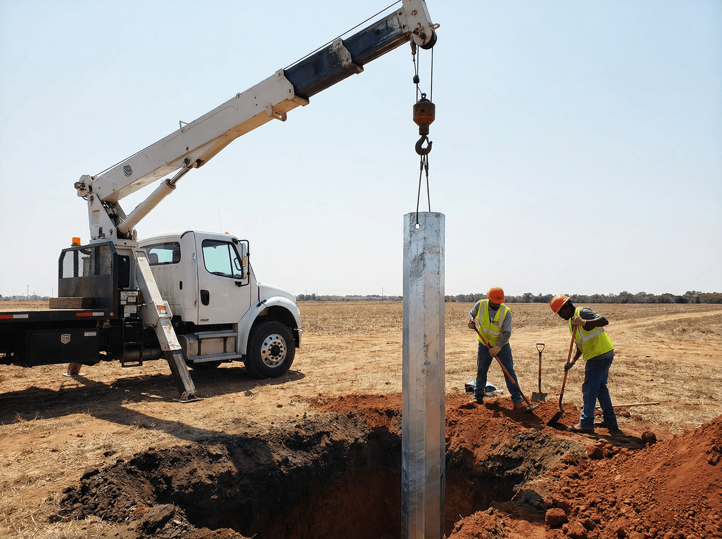
Pole Erection
-
Base Preparation
- Place a compacted gravel or lean concrete pad at the bottom of the hole if required by the geotechnical design.
- Ensure drainage provisions where groundwater is present.
-
Pole Placement
- Lift poles using cranes or truck-mounted equipment with appropriate slings.
- Lower the pole into the hole, aligning orientation for cross arms and line hardware.
-
Backfilling and Compaction
- Backfill with suitable material in layers, compacting each layer to the specified density.
- Check plumbness of the pole during backfilling and adjust as needed.
Hardware and Conductor Installation
-
Attachment of Line Hardware
- Install insulators, cross arms, and hardware according to utility standards and manufacturer instructions.
- Torque bolts to specified values.
-
Stringing of Conductors
- String ACSR-240/30 conductors with tension control to maintain sag within design limits.
- Install spacers, dampers, and other accessories as required.
-
Final Inspection and Commissioning
- Verify clearances, hardware installation, and grounding continuity.
- Perform visual inspection for transport or erection damage to galvanizing.
TIA-222-H (2022) provides additional guidance on erection tolerances and inspection for steel pole structures, which can be referenced by the installation contractor.
Pricing Summary
All pricing is provided on a CIF basis to Port CAUCEDO, using the exact values from quotation TD-2026-0031.
Product 1: 9 m Octagonal Steel Pole
- Pricing basis: CIF
- Port: CAUCEDO
- Unit price: $212.44/ton
- Total price: $25,492.8
Product 2: 10.5 m Octagonal Steel Pole
- Pricing basis: CIF
- Port: CAUCEDO
- Unit price: $345.02/ton
- Total price: $29,326.7
Product 3: 12 m Octagonal Steel Pole
- Pricing basis: CIF
- Port: CAUCEDO
- Unit price: $470.48/ton
- Total price: $28,228.8
Overall Project Pricing
| Product | Quantity | CIF Unit Price (/ton) | CIF Total Price |
|---|---|---|---|
| 9 m Octagonal Steel Pole | 120 sets | $212.44 | $25,492.8 |
| 10.5 m Octagonal Steel Pole | 85 sets | $345.02 | $29,326.7 |
| 12 m Octagonal Steel Pole | 60 sets | $470.48 | $28,228.8 |
Grand Total (all products, CIF): $25,492.8 + $29,326.7 + $28,228.8 = $83,048.3
According to the World Bank (2020), transmission infrastructure can account for 20–30% of total grid investment in developing economies. Optimized pole designs like these from SOLAR TODO help utilities manage capital expenditure while meeting reliability standards.
Conclusion
This Dominican Republic 110 kV project demonstrates how SOLAR TODO’s standardized octagonal steel poles in 9 m, 10.5 m, and 12 m heights can satisfy stringent wind (45 m/s) and seismic (Ss = 0.8 g, S1 = 0.3 g) requirements. All three products achieved conservative stress ratios (≤0.28) and displacement ratios (≤0.56), with direct-burial foundations tailored to each height and a total CIF value of $83,048.3.
FAQ
-
How were the wind loads for these poles determined?
Wind loads were calculated according to ASCE 7-22 using a basic wind speed of 45 m/s and Terrain Category C. The resulting maximum pressures are 1032.9 Pa, 1067 Pa, and 1097.4 Pa for the 9 m, 10.5 m, and 12 m poles respectively, with corresponding top displacements well below their serviceability limits. -
Why was Seismic Design Category C used for this project?
The quotation specifies Ss = 0.8 g and S1 = 0.3 g, which correspond to a moderate-to-high seismic hazard. Under IBC 2024, these values typically place slender steel poles into Seismic Design Category C. All three pole types were checked for this category and reported as PASS in the structural analysis. -
What is the rationale for using direct-burial foundations instead of anchor-bolt foundations?
Direct burial simplifies installation, reduces the number of steel components, and can be cost-effective where soil conditions provide adequate lateral resistance. For this project, borehole sizes range from Ø0.8 × 1.5 m to Ø1.1 × 1.8 m, providing sufficient overturning capacity without anchor bolts, as indicated in the quotation. -
How do the stress ratios ensure long-term reliability?
The highest reported stress ratio is 0.28 for the main leg of the 9 m pole (39 MPa / 141 MPa). Keeping utilization well below 1.0 reduces fatigue and corrosion-fatigue risks, especially in coastal climates. This conservative approach aligns with AISC 360-22 recommendations for structures subjected to cyclic wind and conductor loads. -
Are the three pole heights interchangeable along the line route?
Structurally, each pole is designed for 45 m/s wind and the same seismic parameters, but they have different foundation sizes and clearances. In practice, 9 m, 10.5 m, and 12 m poles are placed according to span length, terrain, and clearance requirements. Interchangeability should follow the line design drawings rather than structural capacity alone. -
What corrosion protection performance can be expected from the hot-dip galvanizing?
All poles are galvanized per ASTM A123. In a typical Caribbean environment, hot-dip galvanizing can provide several decades of protection, often 30–50 years, depending on local pollution and salinity. Regular inspections should be scheduled, but no routine repainting is usually required, which lowers maintenance costs. -
How long does it take SOLAR TODO to produce and deliver these poles?
Each product type has a 21-day production timeline: 2 days for design, 5 for procurement, 7 for fabrication, 3 for galvanizing, 2 for inspection, and 2 for packing. Shipping time to Port CAUCEDO is additional and depends on the logistics schedule, but the manufacturing phase is clearly defined in the quotation. -
Can these pole designs be adapted for different wind speeds or voltages?
Yes. While this project is specifically designed for 110 kV and 45 m/s wind speed, SOLAR TODO routinely adjusts section sizes, wall thicknesses, and foundation dimensions for other wind regimes or voltage levels. The same design methodology—ASCE 7-22 for wind and AISC 360-22 for strength—can be applied to new parameter sets. -
Why was Q235B steel chosen instead of higher-strength grades?
Q235B offers a good balance between strength, weldability, and cost. Given the relatively low stress ratios (≤0.28) achieved in this project, higher-strength steels were not structurally necessary. Using Q235B helps control material and fabrication costs while still meeting all safety and serviceability requirements. -
How is quality documented for the utility’s acceptance process?
For each batch, SOLAR TODO provides EN 10204 3.1 material certificates, welding procedure and welder qualification records (AWS D1.1), galvanizing inspection reports (ASTM A123), and dimensional inspection records. This documentation supports the utility’s technical acceptance and aligns with international best practices.
References
- ASCE (2022). ASCE/SEI 7-22: Minimum Design Loads and Associated Criteria for Buildings and Other Structures. American Society of Civil Engineers.
- ICC (2023). International Building Code 2024 (IBC 2024). International Code Council.
- AISC (2022). AISC 360-22: Specification for Structural Steel Buildings. American Institute of Steel Construction.
- CEN (2006). EN 1993-3-1: Eurocode 3: Design of Steel Structures – Towers, Masts and Chimneys. European Committee for Standardization.
- TIA (2022). TIA-222-H: Structural Standard for Antenna Supporting Structures and Antennas. Telecommunications Industry Association.
- ASTM (2017). ASTM A123/A123M: Standard Specification for Zinc (Hot-Dip Galvanized) Coatings on Iron and Steel Products. ASTM International.
- NREL (2012). Transmission Line Structure Design and Economics. National Renewable Energy Laboratory.
- World Bank (2020). Electricity Transmission and Distribution Investment Needs in Developing Countries. World Bank Group.
- worldsteel (2021). Steel and Corrosion Protection. World Steel Association.
- USGS (2020). Global Seismic Hazard Assessment Program (GSHAP) Data. U.S. Geological Survey.