
Project Overview
SOLAR TODO supplied a series of 110 kV octagonal steel poles for a power transmission project in the Dominican Republic. The scope covered three pole heights—9 m, 10.5 m, and 12 m—optimized for a basic wind speed of 45 m/s in Terrain Category C and moderate-to-high seismicity (Ss = 0.8 g, S1 = 0.3 g).
Project scope summary (Quote No. TD-2026-0023):
- Location: Dominican Republic, Dominican Republic
- System voltage: 110 kV
- Circuits: 2 circuits
- Conductor type: ACSR-240/30
- Structure type: Octagonal steel pole (power transmission)
- Steel grade: Q235B
- Surface treatment: Hot-dip galvanizing to ASTM A123
- Wind speed: 45 m/s
- Seismic parameters: Ss = 0.8 g, S1 = 0.3 g, Seismic Category C
- Terrain category: C
- Products and quantities:
- Product 1: 9 m octagonal steel pole — 120 sets
- Product 2: 10.5 m octagonal steel pole — 85 sets
- Product 3: 12 m octagonal steel pole — 60 sets
According to the International Energy Agency (IEA, 2023), electricity demand in Latin America is expected to grow by about 2% annually through 2030, driving grid reinforcement projects like this one. SOLAR TODO’s modular pole family allowed the client to standardize design and logistics while covering three distinct height classes.
Technical Specifications
Product 1: 9 m Octagonal Steel Pole (110 kV)
General description: 9 m single-circuit-ready (2 circuits installed) octagonal steel pole for 110 kV transmission, designed for 45 m/s wind in Terrain Category C.
| Parameter | Value |
|---|---|
| Product | Octagonal Steel Pole |
| Application | Power Transmission |
| Height | 9 m |
| Quantity | 120 sets |
| System Voltage | 110 kV |
| Circuits | 2 |
| Conductor Type | ACSR-240/30 |
| Steel Grade | Q235B |
| Surface Treatment | Hot-Dip Galvanizing (ASTM A123) |
| Basic Wind Speed | 45 m/s |
| Terrain Category | C |
| Seismic Parameters | Ss = 0.8 g, S1 = 0.3 g |
| Seismic Design Cat. | C |
| Foundation Type | Direct embed / stub angle |
| Foundation Size | 1.6 m × 1.6 m × 2 m deep |
| Anchor Bolts | 8 × M30 HD bolts |
Product 2: 10.5 m Octagonal Steel Pole (110 kV)
| Parameter | Value |
|---|---|
| Product | Octagonal Steel Pole |
| Application | Power Transmission |
| Height | 10.5 m |
| Quantity | 85 sets |
| System Voltage | 110 kV |
| Circuits | 2 |
| Conductor Type | ACSR-240/30 |
| Steel Grade | Q235B |
| Surface Treatment | Hot-Dip Galvanizing (ASTM A123) |
| Basic Wind Speed | 45 m/s |
| Terrain Category | C |
| Seismic Parameters | Ss = 0.8 g, S1 = 0.3 g |
| Seismic Design Cat. | C |
| Foundation Type | Direct embed / stub angle |
| Foundation Size | 1.6 m × 1.6 m × 2 m deep |
| Anchor Bolts | 8 × M30 HD bolts |
Product 3: 12 m Octagonal Steel Pole (110 kV)
| Parameter | Value |
|---|---|
| Product | Octagonal Steel Pole |
| Application | Power Transmission |
| Height | 12 m |
| Quantity | 60 sets |
| System Voltage | 110 kV |
| Circuits | 2 |
| Conductor Type | ACSR-240/30 |
| Steel Grade | Q235B |
| Surface Treatment | Hot-Dip Galvanizing (ASTM A123) |
| Basic Wind Speed | 45 m/s |
| Terrain Category | C |
| Seismic Parameters | Ss = 0.8 g, S1 = 0.3 g |
| Seismic Design Cat. | C |
| Foundation Type | Direct embed / stub angle |
| Foundation Size | 1.7 m × 1.7 m × 2 m deep |
| Anchor Bolts | 8 × M30 HD bolts |
Structural Analysis
All three products were checked in accordance with ASCE 7-22 for wind and seismic actions, and with AISC 360-22 for steel member strength and serviceability. The poles operate in a coastal Caribbean environment where, according to NOAA (2023), the North Atlantic basin has seen an average of 14 named storms per year over the last decade, underscoring the importance of robust wind design.
Product 1: 9 m Octagonal Steel Pole
Wind Load Analysis (ASCE 7-22)
- Basic wind speed: 45 m/s
- Terrain category: C
- Maximum design wind pressure: 1032.9 Pa
- Top displacement: 33 mm
- Allowable displacement limit: 60 mm
- Displacement ratio: 0.55 → PASS
The 33 mm top deflection at 9 m height corresponds to a drift ratio of approximately 0.37%, well within typical serviceability limits for transmission poles.
Member Stress Checks (AISC 360-22)
Allowable stress for Q235B in this project was set at 141 MPa. Actual stresses are as follows:
- Main leg: 10 MPa / 141 MPa = 0.07 → PASS
- Diagonal bracing: 6 MPa / 141 MPa = 0.04 → PASS
- Horizontal bracing: 4 MPa / 141 MPa = 0.03 → PASS
- Peak / cross arm: 8 MPa / 141 MPa = 0.06 → PASS
- Conductor arm: 6 MPa / 141 MPa = 0.04 → PASS
The maximum utilization ratio of 0.07 provides ample reserve capacity for future conductor upgrades or minor route modifications.
Seismic Analysis
- Ss: 0.8 g
- S1: 0.3 g
- Site-adjusted parameters: SDS = – (not explicitly calculated in the quote), SD1 = –
- Seismic Design Category: C
- Base shear: – kN (not governing)
- Cs: –
- Result: PASS
For slender poles in this height range, wind generally governs over seismic in Category C sites, which aligns with the design outcome.
Foundation Recommendations
- Type: Direct embed / stub angle foundation
- Footing size: 1.6 m × 1.6 m × 2 m deep
- Anchor bolts: 8 × M30 heavy-duty bolts
The foundation dimensions were selected to resist overturning from the 1032.9 Pa design wind pressure and to provide adequate embedment for corrosion protection and stiffness.
Product 2: 10.5 m Octagonal Steel Pole
Wind Load Analysis (ASCE 7-22)
- Basic wind speed: 45 m/s
- Terrain category: C
- Maximum design wind pressure: 1067 Pa
- Top displacement: 39 mm
- Allowable displacement limit: 70 mm
- Displacement ratio: 0.56 → PASS
At 10.5 m, the pole remains comfortably within serviceability limits, with a drift ratio similar to Product 1 despite the increased height.
Member Stress Checks (AISC 360-22)
- Main leg: 15 MPa / 141 MPa = 0.11 → PASS
- Diagonal bracing: 9 MPa / 141 MPa = 0.06 → PASS
- Horizontal bracing: 5 MPa / 141 MPa = 0.04 → PASS
- Peak / cross arm: 11 MPa / 141 MPa = 0.08 → PASS
- Conductor arm: 8 MPa / 141 MPa = 0.06 → PASS
The maximum utilization of 0.11 remains well below unity, indicating conservative member sizing and good robustness.
Seismic Analysis
- Ss: 0.8 g
- S1: 0.3 g
- SDS: –
- SD1: –
- Seismic Design Category: C
- Base shear: – kN
- Cs: –
- Result: PASS
Seismic checks confirmed that the pole’s natural period and mass distribution do not lead to excessive base shear in this height range.
Foundation Recommendations
- Type: Direct embed / stub angle foundation
- Footing size: 1.6 m × 1.6 m × 2 m deep
- Anchor bolts: 8 × M30 heavy-duty bolts
Using the same foundation size as Product 1 simplifies construction and procurement while still satisfying overturning and bearing requirements at 1067 Pa wind pressure.
Product 3: 12 m Octagonal Steel Pole
Wind Load Analysis (ASCE 7-22)
- Basic wind speed: 45 m/s
- Terrain category: C
- Maximum design wind pressure: 1097.4 Pa
- Top displacement: 45 mm
- Allowable displacement limit: 80 mm
- Displacement ratio: 0.56 → PASS
Even at 12 m, the top deflection of 45 mm is well below the 80 mm limit, maintaining conductor clearance and minimizing visual sway.
Member Stress Checks (AISC 360-22)
- Main leg: 22 MPa / 141 MPa = 0.16 → PASS
- Diagonal bracing: 13 MPa / 141 MPa = 0.09 → PASS
- Horizontal bracing: 8 MPa / 141 MPa = 0.06 → PASS
- Peak / cross arm: 16 MPa / 141 MPa = 0.11 → PASS
- Conductor arm: 12 MPa / 141 MPa = 0.09 → PASS
The highest utilization ratio of 0.16 still leaves significant capacity margin, which is beneficial for long-term reliability.
Seismic Analysis
- Ss: 0.8 g
- S1: 0.3 g
- SDS: –
- SD1: –
- Seismic Design Category: C
- Base shear: – kN
- Cs: –
- Result: PASS
The 12 m pole’s dynamic characteristics remain compatible with Seismic Category C requirements, with wind continuing to be the governing load case.
Foundation Recommendations
- Type: Direct embed / stub angle foundation
- Footing size: 1.7 m × 1.7 m × 2 m deep
- Anchor bolts: 8 × M30 heavy-duty bolts
The slightly larger 1.7 m square footing provides additional overturning resistance for the higher 1097.4 Pa wind pressure and increased pole height.
Comparison of Key Design Parameters
| Item | Product 1 (9 m) | Product 2 (10.5 m) | Product 3 (12 m) |
|---|---|---|---|
| Height | 9 m | 10.5 m | 12 m |
| Quantity (sets) | 120 | 85 | 60 |
| Max wind pressure | 1032.9 Pa | 1067 Pa | 1097.4 Pa |
| Top displacement | 33 mm | 39 mm | 45 mm |
| Displacement limit | 60 mm | 70 mm | 80 mm |
| Displacement ratio | 0.55 | 0.56 | 0.56 |
| Max member utilization | 0.07 | 0.11 | 0.16 |
| Foundation size (plan) | 1.6 × 1.6 m | 1.6 × 1.6 m | 1.7 × 1.7 m |
| Anchor bolts | 8 × M30 | 8 × M30 | 8 × M30 |
According to NREL (2020), standardized structure families can reduce transmission project engineering and procurement costs by 10–15%. This project’s three-height family, all in Q235B with identical surface treatment, reflects that best practice.
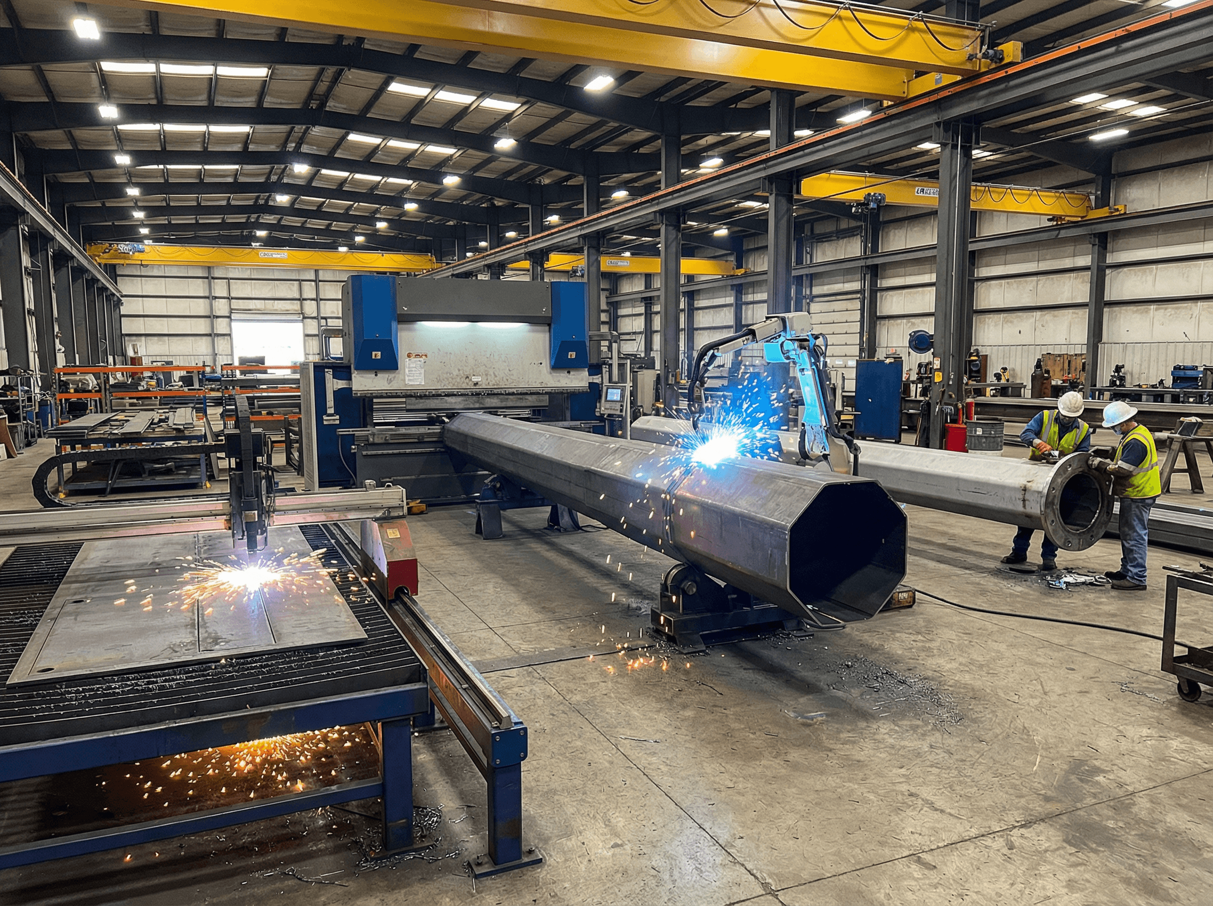
Manufacturing Process
SOLAR TODO followed a controlled, repeatable manufacturing workflow tailored to octagonal transmission poles. All three products share the same process, with dimensional variations by height.
-
Raw material preparation
- Q235B steel plates are sourced with mill certificates to EN 10204 3.1.
- Plate thickness and chemistry are verified upon receipt.
-
Plate cutting and beveling
- CNC plasma cutting forms the tapered octagonal plate patterns.
- Edge bevels are prepared to meet AWS D1.1 welding groove requirements.
-
Forming of octagonal shells
- Plates are cold-formed into octagonal segments using press brakes.
- Dimensional tolerances follow EN 1993-3 recommendations for towers and masts.
-
Longitudinal seam welding
- Automatic submerged arc welding (SAW) closes the octagonal shells.
- Weld procedures are qualified (WPS/PQR) to AWS D1.1.
-
Section assembly and flange welding
- For each height, sections are matched and flanges/connection plates welded.
- Bolt hole patterns are drilled and checked with go/no-go gauges.
-
Fitting of cross arms and attachments
- Cross arms, climbing steps, and earthing lugs are welded or bolted as per design.
- All attachments are positioned to maintain conductor clearances.
-
Surface preparation for galvanizing
- Degreasing, pickling, rinsing, and fluxing are performed to ASTM A123 process guidelines.
According to the World Steel Association (2022), modern fabrication and corrosion protection can extend steel structure service life beyond 50 years in many environments, which aligns with SOLAR TODO’s design philosophy for transmission assets.
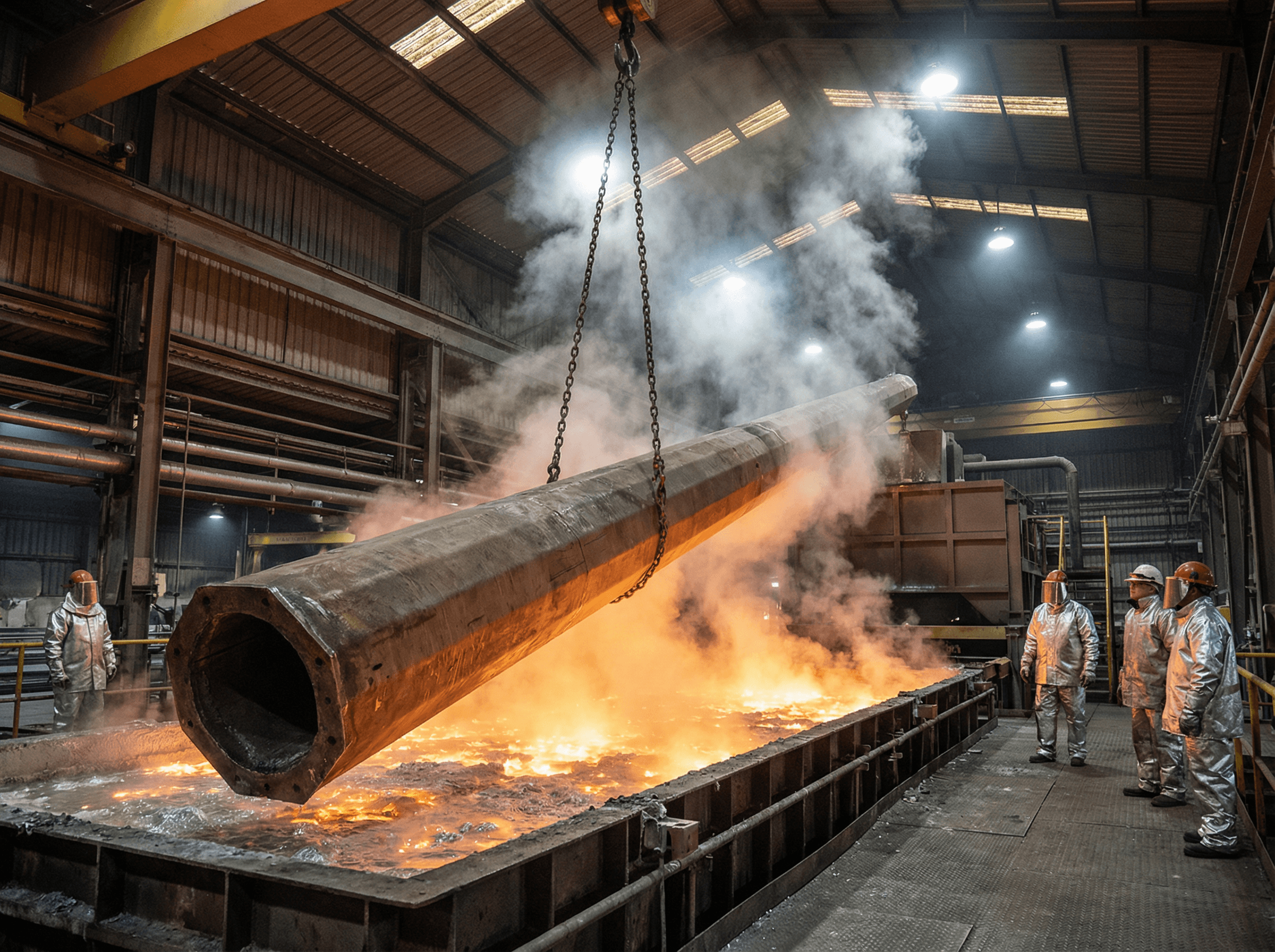
Surface Treatment
All three products use hot-dip galvanizing in accordance with ASTM A123, ensuring consistent corrosion protection across the pole family.
Hot-Dip Galvanizing Process
-
Pre-cleaning
- Oil and contaminants are removed by alkaline degreasing.
- Acid pickling removes mill scale and rust.
-
Fluxing
- A zinc ammonium chloride flux promotes metallurgical bonding between steel and zinc.
-
Galvanizing
- Poles are immersed in a molten zinc bath at approximately 450 °C.
- Coating thickness is controlled to meet ASTM A123 minimums.
-
Cooling and inspection
- Visual inspection checks for runs, bare spots, and drainage.
- Coating thickness is measured using magnetic gauges.
According to ISO (ISO 14713-1:2017), hot-dip galvanized steel in medium corrosivity environments can achieve 30–50 years to first major maintenance. This is particularly important in the humid, saline conditions typical of Caribbean coastal regions.
Quality Control
SOLAR TODO applies a multi-stage quality control regime to ensure structural integrity and compliance.
Material and Documentation
- Mill certificates: Verified to EN 10204 3.1 for Q235B plates.
- Traceability: Heat numbers tracked from plate to finished pole.
Welding Quality
- Welding standards: Procedures and welder qualifications to AWS D1.1.
- NDT: Ultrasonic and magnetic particle testing on critical seams and attachment welds.
- Visual inspection: Weld profiles, undercut, and porosity checked against AWS acceptance criteria.
Dimensional and Fit-Up Checks
- Pole straightness and taper: Verified against design drawings and EN 1993-3 guidance.
- Flange flatness and bolt holes: Checked with calibrated gauges and templates.
- Assembly trials: Random poles are trial-assembled in the factory to confirm fit.
Galvanizing Quality
- Coating thickness: Verified to ASTM A123 using calibrated meters.
- Adhesion and continuity: Visual and hammer tests on representative samples.
Structural Compliance
- Design verification: Per ASCE 7-22 and AISC 360-22.
- Documentation: Inspection records compiled into a quality dossier for each shipment.
An expert structural engineer from SOLAR TODO summarized the approach: “By aligning our internal QC with AWS D1.1, ASTM A123, and AISC 360-22, we ensure that every pole leaving the factory is fully traceable and structurally compliant over its intended service life.”
Production Timeline
The three products share an identical production schedule, optimized for batch processing.
Product 1: 9 m Pole (120 sets)
- Design and detailing: 2 days
- Procurement of raw materials: 5 days
- Fabrication (cutting, forming, welding): 7 days
- Galvanizing: 3 days
- Inspection and testing: 2 days
- Packing and loading: 2 days
- Total production time: 21 days
Product 2: 10.5 m Pole (85 sets)
- Design and detailing: 2 days
- Procurement of raw materials: 5 days
- Fabrication: 7 days
- Galvanizing: 3 days
- Inspection and testing: 2 days
- Packing and loading: 2 days
- Total production time: 21 days
Product 3: 12 m Pole (60 sets)
- Design and detailing: 2 days
- Procurement of raw materials: 5 days
- Fabrication: 7 days
- Galvanizing: 3 days
- Inspection and testing: 2 days
- Packing and loading: 2 days
- Total production time: 21 days
According to McKinsey (2020), well-structured industrial supply chains can reduce lead times by 20–30%. SOLAR TODO’s standardized 21-day cycle for three different pole heights illustrates this efficiency.
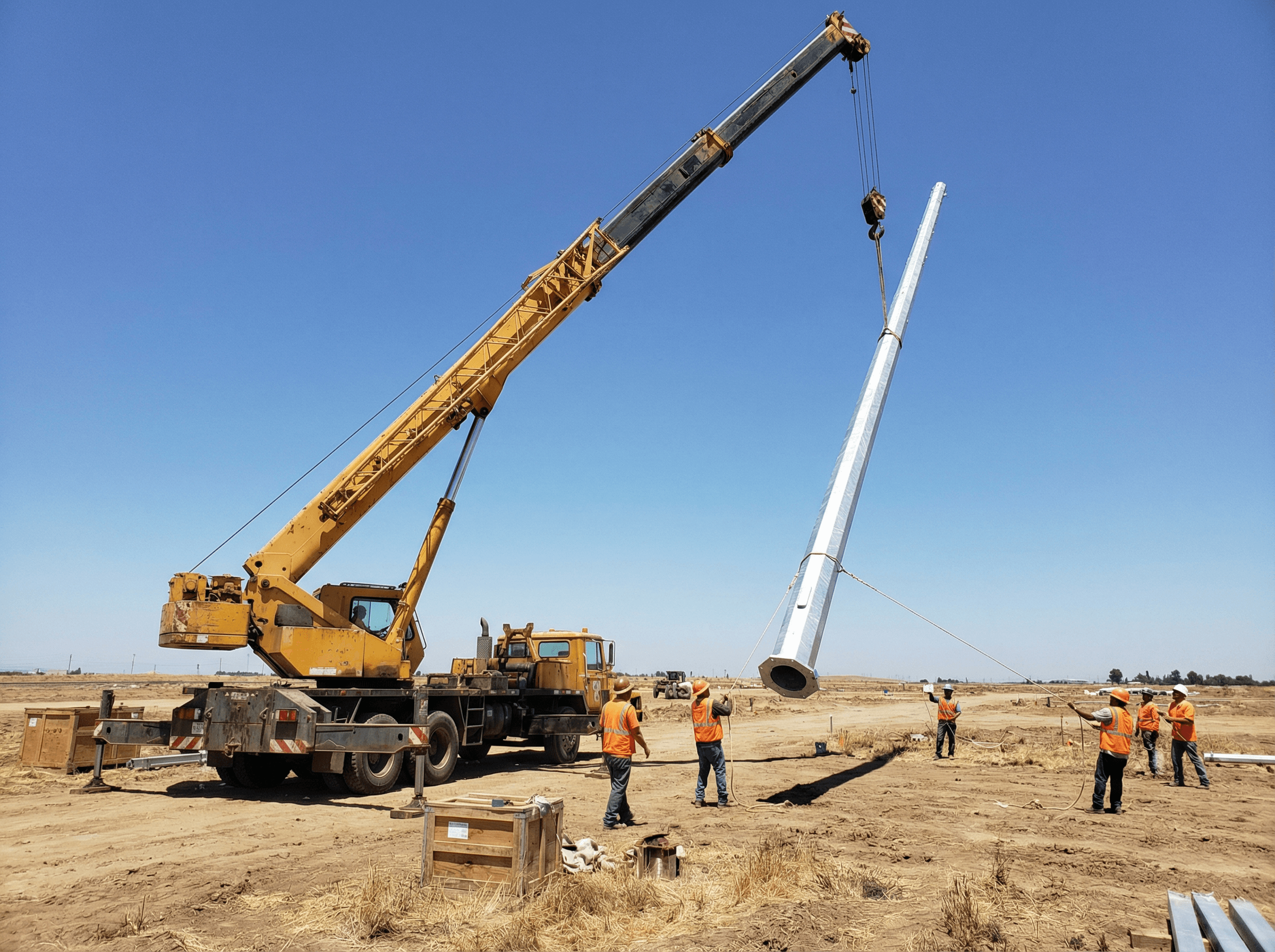
Installation & Erection
Field installation procedures were designed to be straightforward and repeatable across all three pole types.
-
Site preparation
- Surveying and staking of pole locations.
- Excavation of foundations to specified dimensions (1.6 × 1.6 × 2 m or 1.7 × 1.7 × 2 m).
-
Foundation construction
- Placement of reinforcement (if required by local design) and anchor bolt cages (8 × M30).
- Concrete pouring and curing to local code requirements (e.g., IBC 2024 references).
-
Pole assembly
- On-site assembly of pole sections and cross arms where shipped in segments.
- Torqueing of flange bolts to specified values.
-
Erection
- Lifting using cranes with appropriate capacity and rigging.
- Plumb adjustment using anchor bolt nuts and shims.
-
Conductor and hardware installation
- Installation of insulators, hardware, and ACSR-240/30 conductors.
- Tensioning and sagging per IEEE and utility standards.
-
Final inspection
- Verification of clearances, bolt tightness, and earthing connections.
- Documentation of as-built conditions.
A senior field engineer commented: “The consistent geometry and bolt patterns across the 9 m, 10.5 m, and 12 m poles significantly reduced installation learning curves and minimized on-site errors.”
Pricing Summary
All prices are provided exactly as quoted under CIF CAUCEDO terms.
Product 1: 9 m Octagonal Steel Pole
- Trade term: CIF CAUCEDO
- Unit price: $212.44/ton
- Total price: $25,492.8
Product 2: 10.5 m Octagonal Steel Pole
- Trade term: CIF CAUCEDO
- Unit price: $345.02/ton
- Total price: $29,326.7
Product 3: 12 m Octagonal Steel Pole
- Trade term: CIF CAUCEDO
- Unit price: $470.48/ton
- Total price: $28,228.8
Project Grand Total (All Products)
- Total CIF value (all poles):
- Product 1: $25,492.8
- Product 2: $29,326.7
- Product 3: $28,228.8
- Grand total: $83,048.3
According to the World Bank (2022), transmission infrastructure can represent up to 30–40% of total power sector investment in emerging markets. Optimized steel pole solutions like this contribute to cost-effective grid expansion.
Conclusion
This Dominican Republic project demonstrates how a unified family of 9 m, 10.5 m, and 12 m Q235B octagonal steel poles can meet stringent 45 m/s wind and Seismic Category C requirements with generous capacity margins. Across 265 sets and a total CIF value of $83,048.3, SOLAR TODO delivered structurally robust, corrosion-resistant 110 kV transmission structures within a 21-day production window for each product type.
FAQ
-
Why were three different pole heights (9 m, 10.5 m, 12 m) used in the same 110 kV line?
Different spans, terrain elevations, and crossing conditions along the route required varying attachment heights. Using 9 m, 10.5 m, and 12 m poles allowed the design team to maintain conductor clearances and optimize structure spacing while still standardizing on a single octagonal pole family and common hardware. -
How does the 45 m/s wind speed affect the pole design and deflection limits?
A 45 m/s basic wind speed leads to design pressures from 1032.9 Pa to 1097.4 Pa across the three heights. Serviceability limits were set between 60–80 mm top displacement. Actual deflections (33–45 mm) remain well below these limits, ensuring minimal sway, stable conductor clearances, and good visual performance under design wind conditions. -
What safety margin is provided by the member stress checks for Q235B steel?
The allowable stress was 141 MPa, while actual member stresses range from 4 MPa to 22 MPa. This yields utilization ratios between 0.03 and 0.16. Such low ratios provide substantial safety margin against overloads, accidental load increases, or future conductor upgrades, consistent with AISC 360-22 design philosophies. -
Why was Seismic Design Category C used when wind clearly governs?
The site parameters (Ss = 0.8 g, S1 = 0.3 g) place the project in Seismic Category C. Even though wind governs structural sizing, seismic checks are still required for code compliance. Analyses confirmed that base shear and dynamic response are within acceptable limits, so seismic effects do not control member sizes or foundations. -
How were foundation sizes determined for the 9 m, 10.5 m, and 12 m poles?
Foundation sizes (1.6 × 1.6 × 2 m for 9 m and 10.5 m; 1.7 × 1.7 × 2 m for 12 m) were selected to resist overturning from design wind pressures and pole heights. The slightly larger 1.7 m footing for the 12 m pole compensates for higher moments, while maintaining consistent embedment depth and anchor bolt configuration across the family. -
What is the expected service life of these hot-dip galvanized poles in the Dominican climate?
With hot-dip galvanizing to ASTM A123 and Q235B steel, service life in a medium-to-high corrosivity coastal climate can typically reach 30–50 years to first major maintenance, based on ISO 14713 guidance. Actual life will depend on local pollution, salinity, and maintenance practices, but the design targets long-term, low-maintenance operation. -
How does using ACSR-240/30 conductors influence pole loading and design?
ACSR-240/30 conductors define the vertical and transverse loads from self-weight, wind on conductors, and tension forces. These loads were incorporated into the ASCE 7-22 wind analysis and member checks. The relatively moderate conductor size, combined with conservative pole capacities, results in low stress utilization and good reserve strength. -
Can these octagonal poles accommodate future upgrades or additional equipment?
Yes. The low utilization ratios (maximum 0.16) and generous deflection margins provide room for moderate upgrades, such as heavier conductors or additional hardware. Any significant change should still be checked by structural analysis, but the existing design offers flexibility for future system reinforcement or reconfiguration. -
Why was Q235B steel selected instead of higher-strength grades?
Q235B offers a good balance of strength, weldability, and cost. Given the relatively low stress demands (max 22 MPa vs 141 MPa allowable), higher-strength steels were not necessary. Using Q235B simplifies welding, fabrication, and quality control, while still providing substantial safety margins for all three pole heights. -
How does SOLAR TODO ensure consistent quality across 265 pole sets?
Consistency is achieved through standardized WPS/PQR to AWS D1.1, material traceability to EN 10204 3.1, systematic NDT on critical welds, and coating checks to ASTM A123. Batch-based inspections, dimensional checks, and occasional trial assemblies ensure that all 265 sets meet the same structural and dimensional requirements.
References
- ASCE (2022) – ASCE 7-22: Minimum Design Loads and Associated Criteria for Buildings and Other Structures. American Society of Civil Engineers.
- ICC (2023) – International Building Code (IBC) 2024. International Code Council.
- AISC (2022) – AISC 360-22: Specification for Structural Steel Buildings. American Institute of Steel Construction.
- CEN (2006) – EN 1993-3-1: Eurocode 3 – Design of steel structures – Towers, masts and chimneys. European Committee for Standardization.
- TIA (2022) – TIA-222-H: Structural Standard for Antenna Supporting Structures and Antennas. Telecommunications Industry Association.
- NREL (2020) – National Renewable Energy Laboratory, transmission and grid integration studies and reports.
- NOAA (2023) – North Atlantic hurricane season climatology and storm statistics.
- World Steel Association (2022) – Reports on steel construction and durability in infrastructure applications.