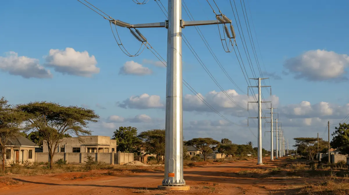
SOLAR TODO delivered a high-reliability Power Transmission Tower package for a 110kV double-circuit transmission line corridor in Dar es Salaam, Tanzania (Latitude -6.79, Longitude 39.28). The scope centered on steel tubular transmission poles designed for heavy wind exposure and long service life in coastal conditions—without relying on lattice structures or FRP components.
Answer Capsule: SOLAR TODO installed 219 steel tubular monopoles—30m, 110kV double-circuit—with ACSR 120 conductors and IEC 60826/GB 50545 wind design, strengthening grid capacity across ~55km.
Project Background: Transmission Growth Meets Coastal Wind Risk
Dar es Salaam’s electricity demand continues to rise as the city expands and industrial activity intensifies along the transmission corridor. For utilities, the challenge is not only adding capacity, but doing so with towers and foundations that remain stable under repeated coastal weather cycles—strong gusts, salt-laden winds, and variable soil conditions.
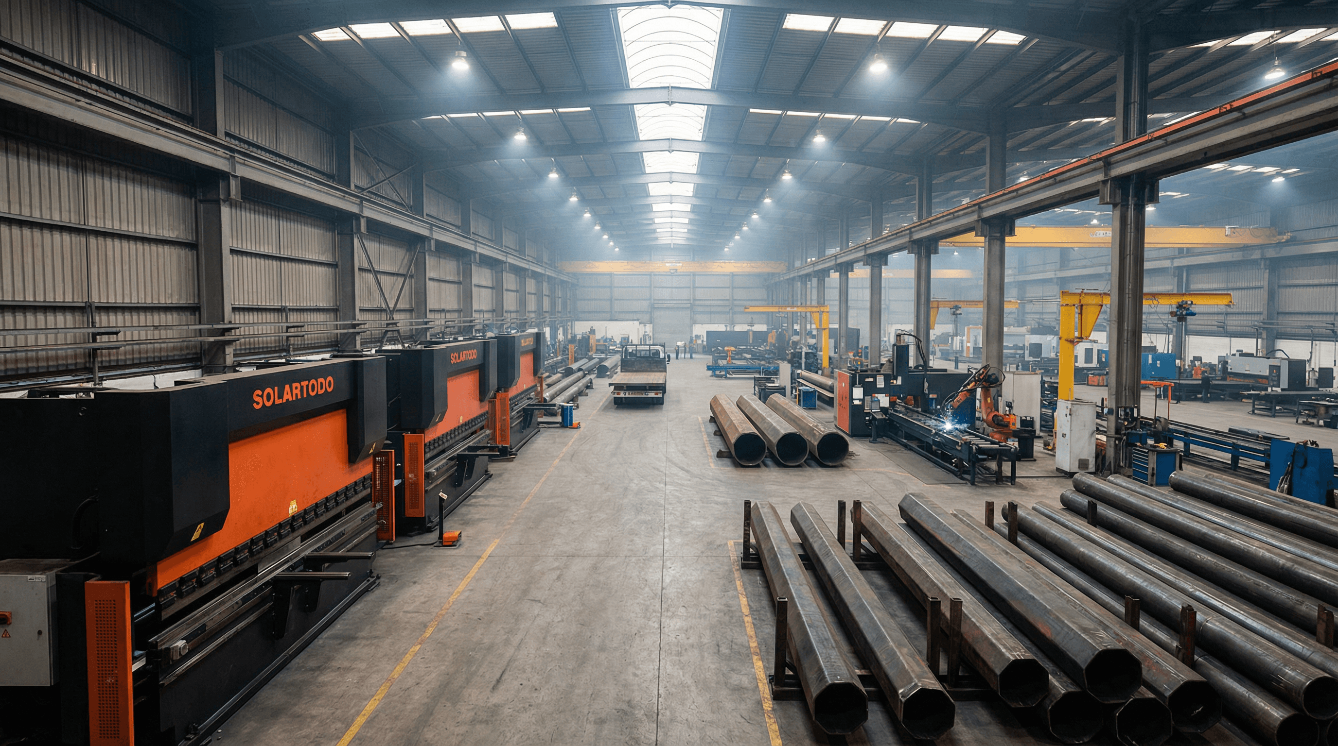
In this project, SOLAR TODO’s design and fabrication approach focused on a robust structural system: a non-lattice, tapered steel tubular monopole using hot-dip galvanized Q345 steel and anchor-bolt concrete foundations. The result was a uniform tower family that could be manufactured, shipped, erected, and commissioned efficiently for a long line length (approximately 55km) with consistent mechanical performance.
Local infrastructure realities also shaped execution. Dar es Salaam’s transport logistics require equipment that can be handled with predictable lifting procedures and modular bolted assembly. The selected pole configuration—flanged bolt sections—supports field erection without the complexity of lattice systems, helping reduce installation time and variability.
Product Solution: Steel Tubular Transmission Pole for 110kV Double Circuit
The core product was the Steel Tubular Transmission Pole (NOT lattice): a 25–40m tapered round or dodecagonal steel monopole. For this deployment, SOLAR TODO supplied a standardized 30m tapered steel tubular pole for 110kV double-circuit line work.
Each pole was engineered to carry insulator strings and ACSR conductors with defined clearances and spacing. The design also incorporated key accessories required for safe operation and maintenance in real-world line environments.
Deployment Overview in Dar es Salaam
SOLAR TODO delivered and supported installation for:
- 219 units × 30m tapered steel tubular pole
- 110kV double circuit line configuration
- Phase spacing: 4m
- Ground clearance: 6m
- Span: 250m
- Total line length: ~55km
The line mechanical design considered wind class 4 conditions: 40 m/s wind speed, aligned with IEC 60826. The pole structure and hardware were produced to satisfy IEC 60826 / GB 50545 requirements for structural loads and wind effects.
Conductor and Insulation Configuration
The conductor selection and string geometry were integral to the pole design:
- Conductor: ACSR 120
- Conductor mass: 470 kg/km
- Max tension: 38 kN
- Insulator length: 1.5m
This configuration was matched to the pole’s cross-arm bracket arrangement for insulator strings and ACSR conductors, ensuring consistent mechanical alignment across the full route.
Foundation and Erection Strategy
For stability and durability under long-term service, each pole used a concrete foundation with anchor_bolt. The foundation system was designed to work with the pole’s flanged bolt sections, which enable controlled assembly and tightening during erection.
Accessories supplied with the pole package included:
- climbing steps (for inspection and maintenance access)
- cross arm (for insulator string support and conductor positioning)
- grounding (for electrical safety and lightning/grounding performance)
- bird guard (to reduce flashover risk and protect insulator zones)
- vibration damper (to mitigate conductor oscillation effects)
Manufacturing Standards and Quality Control
SOLAR TODO’s fabrication followed the applicable structural and wind standards:
- IEC 60826 (overhead line structure loading and wind effects)
- GB 50545 (technical code for overhead transmission line structure design)
Material selection and corrosion protection were also critical for Dar es Salaam’s coastal environment:
- Hot-dip galvanized Q345 steel
- Weight: ~1000 kg/m (projected), resulting in ~30t/pole for the 30m height
Technical Specifications
- Quantity: 219 units
- Pole height: 30m (tapered steel tubular monopole)
- Voltage class: 110kV, double circuit
- Structure type: Steel tubular transmission pole (NOT lattice, NOT FRP)
- Material: Hot-dip galvanized Q345 steel
- Pole geometry: tapered round or dodecagonal steel tubular monopole (project-family within SOLAR TODO tubular spec)
- Weight:
30t/pole (1000kg/m) - Phase spacing: 4m
- Ground clearance: 6m
- Conductor: ACSR 120
- Conductor mass: 470kg/km
- Max tension: 38kN
- Insulator length: 1.5m
- Span: 250m
- Total line length: ~55km
- Wind class: 4 (40 m/s, IEC 60826)
- Foundation: concrete with anchor_bolt
- Accessories: climbing steps, cross arm, grounding, bird guard, vibration damper
- Design standards: IEC 60826 / GB 50545
Why the Steel Tubular Monopole Performed Well
1) Wind-resilient design for IEC 60826 class 4
Dar es Salaam’s coastal conditions can produce high wind gusts. The pole family was designed for wind class 4 (40 m/s) per IEC 60826, supporting predictable load paths under lateral wind pressure and conductor-induced forces.
2) Corrosion protection with hot-dip galvanized Q345
Long-term reliability in coastal climates depends on corrosion resistance. The use of hot-dip galvanized Q345 steel provides a durable protective layer suitable for years of exposure, helping maintain structural integrity and reduce maintenance frequency compared to less corrosion-tolerant alternatives.
3) Mechanical capacity matched to ACSR 120
The transmission configuration centered on ACSR 120 conductors with 470 kg/km mass and 38 kN maximum tension. The pole’s cross-arm brackets and overall structural design were coordinated to handle these mechanical demands while maintaining the specified clearances: 4m phase spacing and 6m ground clearance.
4) Erection efficiency via flanged bolt sections
Instead of complex lattice assembly, the project used flanged bolt sections for controlled field erection. This reduced variability during installation, supported safe assembly sequences, and simplified quality checks on bolted joints.
Results and Impact
Across the corridor, SOLAR TODO’s 219×30m steel tubular poles enabled consistent mechanical performance along a ~55km 110kV double-circuit line with 250m spans.
Key outcomes from the deployment included:
- Standardized tower family: 219 units manufactured under the same tubular geometry and wind design basis, improving uniformity across the route.
- Clearance compliance: Design parameters such as 4m phase spacing and 6m ground clearance were maintained as a consistent system requirement.
- Operational robustness under wind class 4: Structures were engineered for 40 m/s wind conditions per IEC 60826, supporting stable operation during adverse weather.
- Maintenance-ready access and protection: Included climbing steps, grounding, bird guard, and vibration dampers to address real-world inspection and environmental risks.
- Foundation stability with anchor_bolt: Concrete foundations built around anchor-bolt interfaces supported long-term structural anchorage.
Pricing & Quotation
SOLAR TODO offers three pricing tiers for this product line: FOB Supply (equipment ex-works China), CIF Delivered (including ocean freight and insurance), and EPC Turnkey (fully installed, commissioned, with 1-year warranty). Volume discounts are available for large-scale deployments. Configure your system online for an instant estimate, or request a custom quotation from our engineering team at [email protected].
Frequently Asked Questions
1) Why did SOLAR TODO choose a steel tubular monopole instead of a lattice tower for Dar es Salaam?
For this 110kV corridor, SOLAR TODO used a steel tubular transmission pole (NOT lattice, NOT FRP) to improve structural uniformity, simplify erection with flanged bolt sections, and deliver a wind-resilient tubular geometry designed to IEC 60826 / GB 50545 requirements.
2) What conductors and clearances were used on the 110kV double-circuit line?
The line used ACSR 120 conductors (max tension 38 kN, mass 470 kg/km) with insulator length 1.5m. The system maintained 4m phase spacing and 6m ground clearance across the corridor.
3) What wind conditions were considered for tower design?
The project was designed for wind class 4 (40 m/s) according to IEC 60826, supporting predictable lateral loading performance under coastal gust events.
4) What foundation type supports the poles in this project?
Each pole was installed on a concrete foundation with anchor_bolt, providing structural anchorage compatible with the pole’s bolted section assembly approach.
References
- IEC 60826 — Overhead lines — Requirements and tests for the design of overhead transmission lines.
- GB 50545 — Technical code for overhead transmission line structure design.
- IEEE Std 693 — (General guidance) for transmission line structure design and reliability considerations.
- NREL — Transmission and interconnection planning resources (for grid reliability context and line performance considerations).
- World Bank — Infrastructure and power systems reliability guidance relevant to utility asset resilience.
For further details on the Power Transmission Tower product family, visit: Power Transmission Tower product page and contact us.
Equipment Deployed
- 219× 30m tapered steel tubular transmission poles for 110kV double-circuit line (NOT lattice, NOT FRP), hot-dip galvanized Q345 steel, flanged bolt sections, ~30t/pole (~1000kg/m), IEC 60826 / GB 50545 wind design basis
- ACSR 120 conductor set per tower design (470kg/km mass; max tension 38kN) with insulator strings (1.5m insulator length) and 4m phase spacing / 6m ground clearance configuration
- Pole accessories package: cross arm, grounding system, bird guard, vibration damper, and climbing steps
- Concrete foundation system with anchor_bolt for each pole location