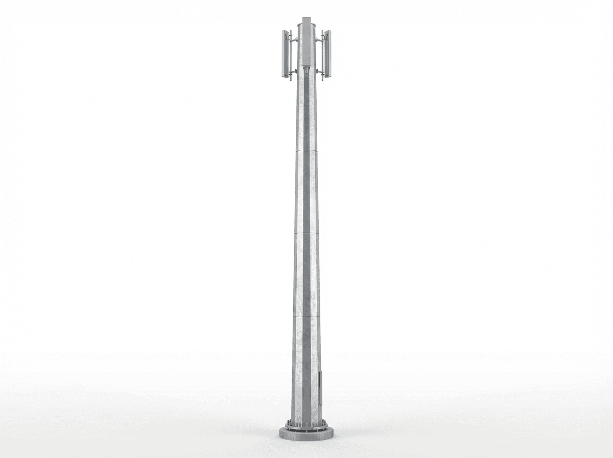
50m Highway Coverage Monopole Slip-Joint - 4-Platform Steel Telecom Tower
Key Features
- 50 m steel monopole with slip-joint sections designed for 50 m/s wind conditions
- 4 antenna platforms supporting up to 12 antennas for approximately 5 km highway coverage
- Compact monopole footprint can reduce occupied ground area by 40% to 70% versus 45-50 m lattice alternatives
- Hot-dip galvanized steel tube structure with 30-year design life and grounding resistance target below 4 ohms
- EPC turnkey pricing ranges from USD 81,000 to USD 108,000 with 1-year warranty included
The 50m Highway Coverage Monopole Slip-Joint is a tubular steel telecom tower engineered for 50 m/s wind regions, 4 antenna platforms, and up to 12 antennas for approximately 5 km highway coverage. Built with hot-dip galvanized steel tube sections, slip-joint connections, and a 30-year design life, it is optimized for fast EPC deployment where land footprint, roadside safety, and network uptime are critical.
Description
The 50m Highway Coverage Monopole Slip-Joint is a 50-meter tubular steel telecom tower designed for highway coverage, 4 antenna platforms, and up to 12 antennas under a 50 m/s design wind regime. This monopole configuration uses slip-joint steel tube sections to reduce bolted flange complexity, maintain a compact roadside footprint, and support approximately 5 km coverage radius depending on terrain profile, antenna height, RF planning, and spectrum band. For operators expanding 4G and 5G along expressways, toll roads, logistics corridors, and peri-urban transport routes, this structure provides a practical balance of structural efficiency, installation speed, and long-term corrosion resistance.
Compared with a conventional 3-leg lattice tower of similar 45-50 m height, a monopole typically reduces occupied ground area by roughly 40% to 70%, which is important where right-of-way width may be limited to 6-12 m and civil approvals are time-sensitive. The single-pole geometry also shortens visual width, simplifies fencing layouts, and can reduce installation interfaces from 3 foundation leg positions to 1 central foundation system. According to TIA-222-H, EN 1993-3-1, and common utility corridor design practice, monopoles are widely selected when land cost, access control, and roadside safety offsets are more critical than maximum payload flexibility.
System Architecture
This system is built around equal-length tapered steel tube sections in Q355-class steel tube with hot-dip galvanizing, assembled through slip-joint connections engineered for axial transfer, bending resistance, and field erection efficiency. A typical configuration includes 4 platform levels, 12 panel antenna positions, cable management, lightning air terminal, down conductor, grounding network, aircraft warning provisions, and an external climbing ladder with safety rail. Foundation depth is usually in the 4-6 m range depending on geotechnical report, groundwater level, overturning moment, and local code requirements. For highway projects, operators generally specify 2 to 3 sectors, with 3 to 4 antennas per sector group, plus optional microwave, GPS, and surveillance accessories.
The 50 m elevation improves line-of-sight over noise barriers, overpasses, vegetation, and rolling terrain where lower 30-35 m poles may create dead zones beyond 2-3 km. In transport corridors carrying 10,000 to 100,000 vehicles per day, maintaining uninterrupted mobile coverage supports driver safety, tolling, emergency communication, fleet telematics, and roadside IoT. Industry energy and digital infrastructure studies from IEA 2025, IRENA 2025, and BloombergNEF 2025 all note that transport electrification, connected mobility, and distributed edge communications are increasing the density requirement for reliable roadside telecom assets.

Technical Specifications
For this variant, the primary structural parameters are fixed at 50 m height, monopole type, steel tube material, 4 antenna platforms, 12 antenna capacity, 50 m/s design wind speed, and slip-joint connection type. A realistic total tip and appurtenance load for this configuration is approximately 1,200 kg, assuming 12 panel antennas, mounting frames, feeders, auxiliary brackets, and aviation accessories within standard telecom loading envelopes. The foundation is typically a reinforced concrete pad with anchor bolts, engineered to suit site-specific soil bearing values often ranging from 150 to 250 kPa. Corrosion protection is hot-dip galvanized, with a target design life of 30 years under routine inspection and maintenance.
Structural design follows TIA-222-H for antenna-supporting structures, EN 1993-3-1 for steel towers and masts, and project-specific national requirements where applicable. Grounding design generally targets resistance below 4 ohms, consistent with practical telecom and lightning protection guidance. Lightning protection includes 1 air terminal, 1 down conductor path, and a buried grounding ring or radial earth electrode arrangement. For quality planning, buyers commonly request mill certificates, galvanizing thickness inspection, weld records, dimensional reports, and pre-shipment fit-up verification for 100% of major tube sections.
Performance for Highway Coverage
A 50 m monopole is particularly effective for highway corridors because the additional elevation can improve propagation continuity across embankments, interchanges, and service areas. In many 700 MHz, 800 MHz, 900 MHz, 1800 MHz, and 2100 MHz deployments, practical macro coverage along open road alignments may reach around 3-5 km, while capacity-oriented higher bands may use the same structure with shorter inter-site spacing of 1-2 km. The specified 5 km coverage radius should therefore be treated as a planning reference, not a universal RF guarantee, because clutter, downtilt, MIMO configuration, and user density materially affect final cell edge performance.
For roadside digital infrastructure, a monopole also supports multi-service loading with fewer visual elements than wider-base alternatives. A 4-platform layout allows phased tenancy over 3 to 10 years, so operators can install 6 antennas initially and expand toward 12 antennas as traffic grows. This staged approach can reduce first-phase capex by 15% to 25% compared with fully loaded day-one equipment strategies, while preserving structural reserve for future 5G radios, microwave backhaul, or ITS devices. Reference planning approaches from NREL, IEA, and telecom infrastructure market analyses by Wood Mackenzie 2025 support modular asset deployment where utilization ramps over time.
Materials, Corrosion Protection, and Design Life
The tower shaft uses steel tube construction, typically aligned with Q355 mechanical properties, offering a practical combination of strength, weldability, and fabrication repeatability at heights around 50 m. Hot-dip galvanizing provides zinc coating protection suitable for inland, suburban, and many transport environments, with maintenance intervals often assessed every 12 months and more detailed structural review every 3 to 5 years. In moderate atmospheric corrosivity zones, a properly galvanized monopole can achieve 30 years of service life; with coating maintenance and bolt replacement programs, many assets remain operational for 40 years or longer.
Compared with painted carbon steel systems requiring more frequent recoating, galvanized monopoles can reduce corrosion maintenance interventions by approximately 20% to 35% over the first 10 years, depending on climate and de-icing salt exposure. For coastal or highly aggressive environments within 1-3 km of seawater, buyers may specify upgraded coating systems or marine-grade detailing. Standards and guidance from IEC, EN, and national galvanizing associations generally emphasize coating thickness control, drainage vent design, and inspection access as critical to long-term durability.
Foundation, Access, and Safety Systems
A typical foundation for a 50 m monopole consists of a reinforced concrete block or pad with anchor bolts, usually requiring 20-35 m3 of concrete depending on overturning loads and soil conditions. Using the reference cost of about $300/m3, concrete-only foundation material value often falls in the $6,000-$10,500 range before excavation, rebar, formwork, and traffic management. Highway-adjacent projects may also require crash barrier coordination, utility clearance, and lane-control permits, which can add 5% to 12% to civil execution cost versus standard greenfield sites.
Access is usually provided by an external ladder with safety rail over the full 50 m height, plus anti-climbing barrier at approximately 3 m above grade. Based on the reference cost of $15/m, the ladder and safety rail package is around $750 for material benchmarking, excluding tower-integrated fabrication details. Safety systems may include rest platforms, vertical lifeline compatibility, warning signage, and optional CCTV. For operator compliance, installation and maintenance practice should align with local work-at-height rules, lockout procedures, and RF exposure management distances.
Antenna Loading and Expansion Planning
This variant is configured for 12 antennas across 4 platforms, which suits multi-operator or multi-band deployment strategies. A common arrangement is 3 sectors with 4 antennas per sector stack, leaving space for RRUs, combiners, and cable trays. Depending on radio architecture, each panel may weigh 20-45 kg, so antenna-only dead load can range from about 240 kg to 540 kg, with additional bracket, feeder, and accessory loads pushing the practical appurtenance package above 800 kg. Structural reserve should be validated before adding microwave dishes larger than 0.3-0.6 m diameter.
Because highway sites often evolve from voice coverage to data-heavy mobility corridors, futureproofing matters. A tower designed today for 4G/5G NSA can later host 5G SA, C-V2X, traffic cameras, weather sensors, and edge communications equipment if the loading schedule and cable pathways are planned from day one. This is why many EPC buyers request not only current loading analysis but also a 5-year and 10-year expansion matrix. You can Configure your system online to match antenna count, platform spacing, ladder type, and accessory options to your deployment roadmap.
Cloud Monitoring and Smart O&M Integration
Although the monopole itself is a passive structure, modern telecom projects increasingly integrate smart monitoring for power, intrusion, lighting, and environmental alarms. Typical add-ons include door sensors, tilt alarms, grounding continuity checks, aircraft light status, and energy telemetry from hybrid power systems. For highway assets spread across 50-500 km corridors, remote monitoring can reduce routine inspection trips by 20% to 40%, improving O&M efficiency and response time. Broader digital infrastructure trends identified by IEA 2025 and BloombergNEF 2025 show rising demand for remote asset supervision as networks become more distributed.
For operators combining telecom with solar-hybrid or battery-backed power systems, cloud visibility helps track uptime, battery state of charge, and alarm history across dozens of roadside nodes. This is particularly useful where grid reliability is below 99% or where diesel dispatch costs exceed $0.25-$0.40/kWh equivalent. SOLARTODO also publishes related engineering resources; buyers can Learn about topic for deployment guidance and View all Telecom Tower products for alternate heights and structures.

Application Scenario
A transport infrastructure operator in the MENA region deployed 8 units of 50 m monopole towers along a 42 km expressway section to improve emergency call coverage, tolling communications, and 4G data continuity for freight traffic. The previous 35 m support structures left intermittent shadow zones near 2 interchanges and 1 service area, especially during seasonal dust conditions and peak congestion. After upgrading to 50 m monopoles with 3-sector antenna layouts, measured roadside signal continuity improved across roughly 92% of the targeted corridor, while the smaller monopole footprint simplified land use inside restricted right-of-way envelopes.
In that case, the monopole option also reduced steel erection complexity compared with a wider lattice alternative because only 1 central shaft and 1 foundation position required close roadside control. The operator estimated total civil and traffic-management coordination hours were reduced by approximately 18% versus the original lattice concept. Results vary by site, but the example illustrates why monopoles are frequently selected where access windows are short, roadside safety is critical, and visual impact must be minimized.
EPC Investment Analysis and Pricing Structure
For B2B telecom buyers, EPC scope typically includes 5 core packages: engineering, procurement, construction, commissioning, and warranty. Engineering covers structural calculations, foundation drawings, fabrication detailing, and QA documentation. Procurement covers steel tube sections, platforms, ladder system, cable trays, lightning kit, and accessories. Construction includes foundation works, erection, alignment, and site finishing. Commissioning includes grounding verification, torque checks, verticality checks, and handover documents. The standard turnkey package includes a 1-year warranty for supplied and installed scope.
The pricing structure for this 50 m highway monopole is summarized below. FOB applies to equipment supply ex-works China, CIF adds ocean freight and insurance, and EPC Turnkey includes installation and commissioning. For formal project pricing with geotechnical, transport, and local labor inputs, buyers should Request a custom quotation or email [email protected].
| Pricing Tier | Scope | Price Range (USD) |
|---|---|---|
| FOB Supply | Tower steelwork, platforms, ladder, cable tray, lightning accessories, standard documentation | $50,220 - $73,440 |
| CIF Delivered | FOB scope + ocean freight + marine insurance | $64,223 - $93,917 |
| EPC Turnkey | CIF scope + civil works, erection, commissioning, 1-year warranty | $81,000 - $108,000 |
For portfolio buyers, indicative volume discounts can improve total project economics. These discounts usually apply to repeatable tower supply packages rather than highly customized one-off civil scopes.
| Order Volume | Discount |
|---|---|
| 50+ units | 5% |
| 100+ units | 10% |
| 250+ units | 15% |
From an ROI perspective, the value of a 50 m highway monopole is measured less by direct energy savings and more by avoided coverage gaps, lower land-use cost, and reduced deployment complexity compared with larger-footprint structures. If a monopole solution lowers land acquisition, fencing, and traffic-control related costs by even $8,000-$15,000 per site compared with a conventional roadside lattice build, the lifecycle economics can become favorable within the first 1-3 years of network operation. In shared-infrastructure models with 2 tenants, annual lease revenue or cost-sharing can further compress payback toward 3-5 years, depending on local market rates and tenancy ramp.
Payment terms are typically 30% T/T deposit with 70% against B/L for supply contracts, or 100% L/C at sight for qualified transactions. Financing support may be discussed for projects above $1,000,000 in total value, particularly where deployment spans 50+ sites and phased delivery is required. For commercial review, BoQ validation, or EPC planning, contact [email protected].
Why Choose a Slip-Joint Monopole
Slip-joint construction is often selected for 40-50 m monopoles because it reduces the number of large flange interfaces and can streamline fabrication and field assembly. In many cases, fewer major bolted joints translate into shorter erection sequences and lower inspection complexity during installation. Depending on section geometry and crane planning, slip-joint systems may reduce field connection time by approximately 10% to 20% compared with equivalent multi-flange arrangements. That said, final selection should consider transport length limits, erection method, and local contractor familiarity.
For highway agencies and telecom EPC firms, the main advantage is practical constructability. Equal-length tapered sections are easier to standardize across multiple sites, and the single-shaft form is more compatible with constrained roadside compounds of around 3 m footprint plus fenced working area. If your project requires alternate heights, anti-climbing upgrades, or integrated smart power systems, View all Telecom Tower products or Learn about topic for related engineering references.
Procurement Notes for Engineers and Buyers
Before procurement, buyers should confirm 6 key inputs: geotechnical data, design wind speed, antenna schedule, cable routing, grounding target, and transport access. A 50 m/s wind design is robust for many inland and exposed locations, but some coastal or cyclone-prone regions may require higher criteria. The antenna loading schedule should specify current and future equipment over at least 2 phases. Foundation design should not be finalized without soil investigation, because a change from 150 kPa to 90 kPa allowable bearing can materially increase concrete volume and anchor design.
Documentation typically requested in B2B tenders includes GA drawing, section schedule, platform details, galvanizing specification, bolt list, packing list, and installation method statement. For projects with utility or highway authority oversight, additional submissions may include obstruction lighting details, setback compliance, and maintenance access plan. SOLARTODO can support RF-neutral structural supply and EPC coordination for standardized telecom tower packages; to start specification alignment, Request a custom quotation.
Technical Specifications
| Tower Height | 50m |
| Tower Type | monopole |
| Material | steel_tube |
| Antenna Platforms | 4levels |
| Antenna Capacity | 12antennas |
| Design Wind Speed | 50m/s |
| Total Tip Load | 1200kg |
| Foundation Type | Reinforced concrete pad with anchor bolts |
| Connection Type | Slip-joint |
| Coverage Radius | 5km |
| Corrosion Protection | Hot-dip galvanized |
| Design Life | 30years |
| Grounding Resistance Target | <4ohm |
| Standards | TIA-222-H / EN 1993-3-1 |
| Application | Highway coverage |
Price Breakdown
| Item | Quantity | Unit Price | Subtotal |
|---|---|---|---|
| 50m Q355 steel tube monopole shaft (hot-dip galvanized) | 1 pcs | $42,000 | $42,000 |
| Antenna platform assemblies | 4 pcs | $800 | $3,200 |
| Climbing ladder with safety rail | 1 pcs | $750 | $750 |
| Cable tray system | 1 pcs | $500 | $500 |
| Lightning protection system | 1 pcs | $500 | $500 |
| Aircraft warning light set | 1 pcs | $300 | $300 |
| Concrete foundation materials | 1 pcs | $8,400 | $8,400 |
| Engineering & QC | 1 pcs | $6,200 | $6,200 |
| Installation & Commissioning | 1 pcs | $18,250 | $18,250 |
| 1-Year Warranty & Support | 1 pcs | $2,200 | $2,200 |
| Total Price Range | $81,000 - $108,000 | ||
Frequently Asked Questions
What is the main advantage of a 50m monopole for highway coverage?
How many antennas can this tower support?
What does the EPC turnkey price include?
What foundation is typically required for a 50m monopole?
What warranty and payment terms are available?
Certifications & Standards


Data Sources & References
- •TIA-222-H Structural Standard for Antenna Supporting Structures
- •EN 1993-3-1 Eurocode 3 Towers, Masts and Chimneys
- •IEA World Energy Outlook 2025
- •IRENA Renewable Power and Infrastructure Outlook 2025
- •BloombergNEF Digital Energy Infrastructure 2025
- •Wood Mackenzie Telecom Infrastructure Outlook 2025
- •NREL infrastructure siting and energy systems references 2025
Interested in this solution?
Contact us for a customized quote based on your specific requirements.
Contact Us