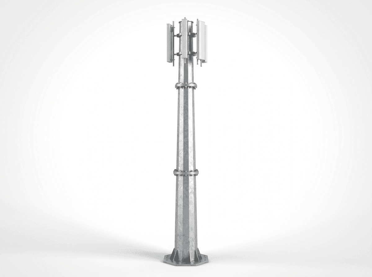
45m Monopole Highway Corridor Flanged - 50 m/s Wind Design
Key Features
- 45 m hot-dip galvanized steel monopole with 30-year design life
- Engineered for 50 m/s wind speed under TIA-222-H and EN 1993-3-1 design practice
- 4 antenna platforms supporting up to 12 antennas for 3-carrier deployment
- Approximate 5 km coverage radius for highway corridor macro network planning
- EPC turnkey budget range of $67,500-$94,500 with 1-year warranty included
The 45m Monopole Highway Corridor Flanged is a galvanized steel tubular telecom tower engineered for 45 m height, 4 antenna platforms, up to 12 antennas, and 50 m/s design wind speed. It is optimized for 3-carrier highway corridor coverage with about 5 km service radius, pile foundation support, and flanged section connections for controlled transport and fast field assembly.
Description
The 45m Monopole Highway Corridor Flanged is a single-tube steel telecom tower designed for highway corridor coverage, with a total height of 45 m, 4 antenna platforms, capacity for 12 antennas, and structural verification for 50 m/s basic design wind speed. In a typical 3-carrier deployment, the tower supports macro 4G/5G sector antennas, optional microwave backhaul, aviation obstruction marking, and grounding systems on a compact footprint that is generally close to 3 m class foundation width while using a pile foundation for difficult roadside geotechnical conditions. For buyers comparing corridor macro sites, this configuration targets about 5 km coverage radius under favorable terrain and is engineered around flanged steel tube sections for repeatable transport, erection, and maintenance cycles over a 30-year design life.
For transport authorities, mobile network operators, and EPC contractors, a 45 m flanged monopole is often the preferred compromise between 20 m urban poles and 60 m+ lattice towers because it offers lower land take, faster assembly, and a cleaner visual profile along controlled-access roads. Compared with a conventional 3-leg lattice tower of similar loading, a monopole can reduce occupied ground area by about 40% to 60%, depending on foundation geometry and access fencing, while simplifying roadside permitting in corridors where every additional 10 m² of land acquisition can increase total project cost. Structural design practice for this product references TIA-222-H, EN 1993-3-1, and project-specific local code checks, while grounding and lightning practices align with widely used telecom and electrical safety principles from IEC and national utility standards.
System Architecture
The system architecture is based on a tapered steel tube monopole fabricated in equal-length transportable sections with flanged connections between major segments. At 45 m overall height, the shaft geometry is optimized to balance self-weight, overturning moment, and antenna eccentricity from up to 12 panel antennas distributed across 4 levels. A typical 3-sector, 3-carrier arrangement uses 9 active panel antennas plus 3 reserve or future-upgrade positions, allowing operators to deploy LTE, NR, and shared infrastructure on one pole while preserving loading margin for RRUs, feeder management, and aviation accessories.
The foundation concept specified here is a pile foundation, typically selected where roadside embankments, variable bearing strata, or drainage-adjacent soils make shallow pads less efficient. Depending on geotechnical report results, monopole pile systems for a 45 m class tower commonly use 4 to 8 reinforced concrete piles with depths often in the 4 m to 12 m range, tied by a pile cap and anchor bolt cage. Final dimensions must be confirmed by soil parameters, groundwater level, and overturning load combinations, but the objective is always to maintain serviceability under the 50 m/s design wind case and operational vibration limits for antenna alignment.
The loading envelope is intended for highway corridor radio coverage where traffic density can justify 3-carrier co-location on a single structure. In practical design terms, the tower can carry 12 antennas, cable ladders, feeder clamps, grounding bars, and optional microwave dishes if permitted by final structural calculations. A reasonable planning allowance for total top and appurtenance load on this configuration is about 1,200 kg, subject to antenna sail area, mount offsets, and local code combinations. Buyers should treat this as a project engineering figure rather than a universal guarantee, because a 0.5 m² increase in antenna projected area at 45 m elevation can materially change base moment and bolt demand.
The monopole is manufactured from Q355 steel tube or equivalent structural steel grade, then protected by hot-dip galvanizing to support long-term outdoor service in highway environments exposed to de-icing salts, dust, and rain cycling. For many transport projects, galvanizing thickness and coating integrity are checked in accordance with relevant steel protection standards, because a 30-year design life depends not only on section thickness but on corrosion management, drainage detailing, and bolt protection. In coastal or highly polluted environments, additional coating systems can be specified to improve durability beyond standard zinc protection.

Technical Specifications
This variant uses flanged section connections instead of slip-joint-only assembly, which is valuable for sites that require controlled bolt-up installation windows, repeatable alignment, and easier replacement of damaged sections after vehicle impact or exceptional events. A flanged joint introduces more fabrication detail and bolt hardware than a slip-fit section, but it also improves erection control where cranes must work within 1 to 2 short traffic closures. For highway corridors, that logistics advantage often outweighs the modest increase in steel and connection cost.
Standard tower accessories typically include an external ladder with safety rail over the full 45 m height, anti-climb barrier starting at about 3 m, cable tray routing, top air terminal, down conductor, and a grounding network designed to achieve resistance below 4 ohms where soil conditions allow. Aviation warning lights are generally added when required by civil aviation rules for structures near flight paths or above local height thresholds, and many operators now specify LED obstruction lights with service intervals exceeding 50,000 hours to reduce maintenance visits.
Antenna platform design is based on 4 levels, each configured for sectorized mounting and technician access. In a common arrangement, each level accommodates 3 antennas, producing the total 12-antenna capacity, although final mounting geometry can be adjusted for mixed 4G/5G panels, microwave brackets, GPS units, and future expansion. Cable management is engineered to maintain bend radius, reduce wind-induced movement, and support safe climbing. For high-band 5G deployments, even a 2 dB feeder loss difference can affect effective coverage, so routing discipline and equipment placement matter as much as structural capacity.
Performance for Highway Corridor Networks
Highway corridor telecom infrastructure must deliver predictable radio continuity over long linear routes, not just high peak throughput at one point. A 45 m monopole improves line-of-sight over rolling terrain, overpasses, and roadside vegetation compared with 20 m to 30 m poles, and can reduce the number of macro sites needed along a 50 km route segment. While actual radio planning depends on frequency band, clutter, and traffic profile, a nominal 5 km coverage radius can be achievable in favorable suburban or open-road conditions, especially in lower and mid-band spectrum. This makes the product suitable for emergency calling coverage, tolling support, ITS backhaul, CCTV connectivity, and public mobile broadband.
According to IEA mobile data growth and digital infrastructure outlooks, traffic demand continues to rise annually by double-digit percentages in many markets, and transport corridors are increasingly treated as strategic digital assets rather than passive rights-of-way. IRENA and BloombergNEF have also highlighted the convergence of power, communications, and smart infrastructure investment, where telecom towers support EV charging management, traffic sensing, and distributed energy control. In that context, a 45 m corridor monopole is not only a telecom support structure but part of a broader roadside digitalization platform with 24/7 network criticality.
Compared with a conventional rooftop deployment every 2 km to 3 km, a dedicated highway monopole can lower dependence on third-party lease negotiations, reduce rooftop structural uncertainty, and improve maintenance access. In many corridor projects, that translates into 15% to 25% lower lifecycle coordination cost over 10 years, even when initial civil works are higher. The reason is operational: a single roadside tower under direct asset control is easier to inspect, upgrade, and secure than multiple leased host structures with different access rules and reinforcement histories.
Materials, Fabrication, and Quality Control
The shaft sections are fabricated from rolled and welded steel tube with dimensional tolerances controlled to ensure flange flatness, bolt-hole alignment, and overall verticality after assembly. For a 45 m monopole, fabrication quality directly affects erection speed because even a 2 mm to 3 mm flange mismatch can slow field alignment and torqueing. SOLARTODO quality workflows typically include material traceability, weld inspection, galvanizing inspection, and trial fit-up checks before shipment. Buyers evaluating multiple suppliers should ask for weld procedure qualification records, galvanizing certificates, and bolt-grade documentation, not only general brochures.
Industry practice for monopole verification includes strength, deflection, fatigue-sensitive details, and serviceability checks under code-defined load combinations. TIA-222-H is widely used for telecom structures in the United States and many export projects, while EN 1993-3-1 is common in Europe and code-influenced international markets. For wind engineering, a 50 m/s design basis is appropriate for many exposed transport corridors, but local gust conversion, return period, topographic amplification, and importance factor must still be reviewed by the project engineer. A difference between 45 m/s and 50 m/s can significantly change section thickness and foundation demand, so code assumptions should be explicit in procurement documents.
Installation and Field Execution
A flanged monopole of 45 m is usually erected by mobile crane in sequential section lifts, followed by platform installation, cable ladder attachment, grounding completion, and antenna integration. Depending on site readiness, a typical structural erection window can be 1 to 3 days, while full civil, electrical, and telecom completion may require 2 to 6 weeks including foundation curing, utility coordination, and commissioning. Along highways, traffic management planning is critical, because crane setup, lane closures, and safety barriers can represent 5% to 12% of total installation cost on constrained sites.
The pile foundation option improves suitability for soft shoulders, embankments, and drainage-prone areas where a shallow pad may require excessive excavation. In some projects, using piles reduces concrete volume by 15% to 30% versus a large mass footing, though reinforcement and drilling costs can offset part of that saving. The correct solution depends on geotechnical data. For procurement teams, the key point is that foundation optimization can change total EPC by more than $8,000 on a single site, so early soil investigation is financially justified.
Applications
This product is engineered for highway corridor use cases including macro cellular coverage, emergency roadside communications, intelligent transportation systems, tolling network support, CCTV backhaul, weather monitoring, and connected mobility infrastructure. A 45 m elevation is especially useful where barriers, sound walls, and interchanges create shadowing that shorter poles cannot overcome. In a typical deployment, 3 carriers share the tower, each using 3 sector antennas, while the remaining 3 positions are reserved for future 5G upgrades, public safety radios, or microwave backhaul.
A practical scenario illustrates the value. A transport-linked telecom operator in the MENA region deployed a corridor package of 18 towers in a 92 km highway section with mixed desert and suburban terrain. By using 45 m flanged monopoles instead of larger lattice towers, the project reduced average site footprint by roughly 48%, shortened average erection time by 2 days per site, and maintained target coverage continuity above 95% for voice and data handover planning. In dusty environments with ambient summer temperatures above 45°C, the galvanized monopole approach also simplified cleaning and visual inspection compared with denser lattice steelwork.

Cloud Monitoring and O&M Considerations
While the monopole itself is a passive structure, most modern corridor projects integrate remote monitoring for power, battery backup, obstruction light status, intrusion alarms, and environmental sensors. A single site can transmit 10 to 50 operational parameters into the operator NOC or smart infrastructure platform, improving fault response times and reducing unnecessary truck rolls. NREL and broader digital O&M studies consistently show that data-driven maintenance can lower field service interventions by 10% to 20% when alarm quality and asset tagging are properly implemented.
Routine maintenance for a 45 m monopole typically includes annual visual inspection, bolt torque verification at scheduled intervals, grounding continuity checks, coating assessment, and accessory inspection. In corrosive or high-vibration environments, a 6-month inspection cycle may be justified for the first 2 years to establish baseline behavior. Lightning protection should be verified after major storm seasons, and grounding resistance should remain below the target threshold, commonly 4 ohms or lower where feasible. These practices support both structural safety and telecom uptime.
For buyers seeking broader technical guidance, see Learn about topic and Learn about topic. To compare related structures and configurations, View all Telecom Tower products, use the engineering tool to Configure your system online, or Request a custom quotation for project-specific loading, foundation, and logistics review.
EPC Investment Analysis and Pricing Structure
For this 45 m highway corridor monopole, EPC scope typically includes 5 major packages: engineering, procurement, construction, commissioning, and warranty. Engineering covers structural calculations, foundation design inputs, drawings, and QC documentation. Procurement covers the steel monopole, platforms, ladder, cable tray, grounding, and accessories. Construction includes foundation works, erection, installation, and site finishing. Commissioning covers alignment, grounding verification, and handover records. The standard turnkey package includes 1-year warranty support after commissioning.
| Pricing Tier | Scope | Price Range (USD) |
|---|---|---|
| FOB Supply | Equipment only, ex-works China | $41,850 - $64,260 |
| CIF Delivered | Equipment + ocean freight + insurance | $53,519 - $82,177 |
| EPC Turnkey | Installed, commissioned, 1-year warranty | $67,500 - $94,500 |
For multi-site corridor rollouts, volume discounts can materially improve total capital efficiency. The standard discount structure is shown below and is usually applied to equipment value first, then adjusted for destination-specific logistics and labor conditions.
| Order Volume | Discount |
|---|---|
| 50+ units | 5% |
| 100+ units | 10% |
| 250+ units | 15% |
From an investment perspective, the ROI case depends on whether the buyer is a carrier, neutral host, or transport authority. Compared with leasing rooftop or third-party host structures along a 50 km route, owning a corridor monopole can save approximately $8,000 to $18,000 per year in recurring lease, access coordination, and upgrade negotiation costs for each strategic site. Against those savings, an EPC cost of $67,500 to $94,500 implies a simple payback of roughly 4 to 9 years, excluding revenue gains from improved coverage, co-location rent, or reduced outage penalties. Where a neutral host secures 2 to 3 tenants, payback can be shorter than 4 years in favorable markets.
Payment terms are typically 30% T/T deposit and 70% against B/L for supply contracts, or 100% L/C at sight for qualified transactions. For corridor programs above $1,000,000, structured financing support may be discussed subject to project credit review, jurisdiction, and order profile. For commercial evaluation, BOQ review, or EPC clarification, contact [email protected].
Technical Specification Summary
The standard specification for this model is summarized below for procurement and engineering reference. Final drawings and calculations should always supersede catalog values when local code, antenna loading, or soil conditions differ.
- Tower Height: 45 m
- Tower Type: Monopole
- Material: Steel tube
- Antenna Platforms: 4 levels
- Antenna Capacity: 12 antennas
- Design Wind Speed: 50 m/s
- Total Tip Load: 1,200 kg
- Foundation Type: Pile foundation
- Corrosion Protection: Hot-dip galvanized
- Design Life: 30 years
- Standards: TIA-222-H / EN 1993-3-1 / GB 50135
Procurement Notes
For tendering, buyers should define at least 8 project variables: exact antenna model list, projected area, mount offsets, microwave dish count, site altitude, basic wind speed, soil report, and grounding target. Omitting any of these can produce under- or over-designed structures and distort EPC comparison by more than 10%. A robust RFQ should also state whether obstruction lighting, anti-climb devices, feeder trays, and paint markings are included.
In summary, the 45m Monopole Highway Corridor Flanged is a high-capacity macro telecom structure for roadside and transport infrastructure projects requiring 45 m height, 4 platform levels, 12 antenna positions, and 50 m/s wind resistance with a compact footprint and flanged modular assembly. It is particularly suitable where operators need 3-carrier sharing, approximately 5 km corridor coverage, and a lifecycle-balanced alternative to larger lattice towers or fragmented rooftop leasing. For project-specific engineering, use the links above to configure, compare, and quote the system through SOLARTODO.
Technical Specifications
| Tower Height | 45m |
| Tower Type | monopole |
| Material | steel_tube |
| Antenna Platforms | 4levels |
| Antenna Capacity | 12antennas |
| Design Wind Speed | 50m/s |
| Total Tip Load | 1200kg |
| Foundation Type | pile_foundation |
| Connection Type | flanged |
| Application | highway_corridor |
| Carrier Sharing | 3carriers |
| Coverage Radius | 5km |
| Corrosion Protection | Hot-dip galvanized |
| Design Life | 30years |
| Standards | TIA-222-H / EN 1993-3-1 / GB 50135 |
Price Breakdown
| Item | Quantity | Unit Price | Subtotal |
|---|---|---|---|
| Q355 steel tube monopole shaft (hot-dip galvanized) | 22 pcs | $1,500 | $33,000 |
| Antenna platform assemblies | 4 pcs | $800 | $3,200 |
| Climbing ladder with safety rail | 45 pcs | $15 | $675 |
| Cable tray system | 45 pcs | $10 | $450 |
| Lightning protection system | 1 pcs | $500 | $500 |
| Aircraft warning light set | 1 pcs | $300 | $300 |
| Pile foundation concrete works | 40 pcs | $300 | $12,000 |
| Anchor bolts, flanges, base hardware, grounding materials | 1 pcs | $4,200 | $4,200 |
| Installation & Commissioning | 1 pcs | $14,500 | $14,500 |
| Engineering & QC | 1 pcs | $6,200 | $6,200 |
| 1-Year Warranty & Support | 1 pcs | $1,800 | $1,800 |
| Total Price Range | $67,500 - $94,500 | ||
Frequently Asked Questions
What makes a 45 m flanged monopole suitable for highway corridor telecom coverage?
Why choose flanged connections instead of slip-joint-only sections?
What foundation is used for this model, and how deep is it typically?
What is included in the EPC turnkey price and warranty?
How does this monopole compare with a conventional lattice tower on lifecycle cost?
Certifications & Standards

Data Sources & References
- •TIA-222-H Structural Standard for Antenna Supporting Structures and Antennas
- •EN 1993-3-1 Eurocode 3 - Towers, masts and chimneys
- •NREL operations and maintenance research references
- •IEA digital infrastructure and energy system outlook references
- •IRENA energy transition and infrastructure integration publications
- •BloombergNEF infrastructure and telecom-energy convergence market analysis
Interested in this solution?
Contact us for a customized quote based on your specific requirements.
Contact Us