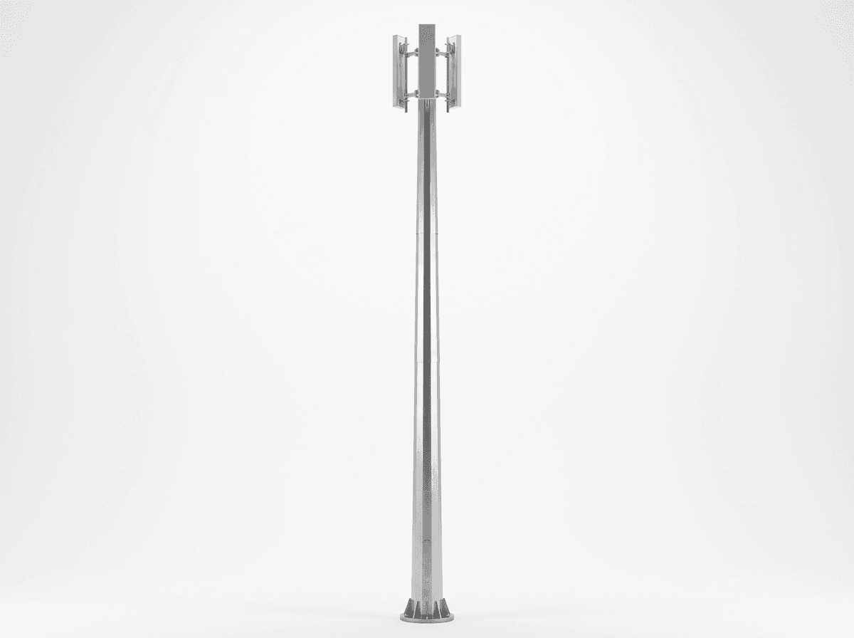
40m Monopole Industrial Zone Coverage Slip-Joint - 3-Platform Steel Telecom Tower
Key Features
- 40 m hot-dip galvanized steel monopole with slip-joint sections for compact industrial-zone deployment
- Supports 3 antenna platforms, 12 antennas, 2 microwave dishes, and 4-carrier colocation
- Designed for 50 m/s wind speed with concrete stub foundation typically 4-6 m deep
- Approximate footprint around 3 m, reducing land use by 50-70% versus comparable lattice towers
- EPC turnkey price range USD 54,000-74,300 with 1-year warranty and commissioning included
The 40m Monopole Industrial Zone Coverage Slip-Joint is a tubular steel telecom tower engineered for 3 antenna platforms, up to 12 antennas, 2 microwave dishes, and 50 m/s design wind speed. Built with hot-dip galvanized steel tube sections and a concrete stub foundation, it supports 4-carrier industrial-zone coverage with EPC turnkey pricing from USD 54,000 to USD 74,300.
Description
The 40m Monopole Industrial Zone Coverage Slip-Joint is a 40-meter tubular steel telecom tower designed for industrial-zone wireless coverage, 4-carrier colocation, and 12 antenna loading with 2 microwave dishes under a 50 m/s design wind regime. This monopole uses equal-length tapered steel tube sections, a slip-joint connection, and a concrete stub foundation to deliver a compact footprint of about 3 meters while maintaining a 30-year design life. For buyers comparing options across the View all Telecom Tower products, this configuration fits projects requiring high structural efficiency, fast installation, and lower land-use intensity than 3-leg lattice towers of similar 40 m height.
In industrial estates, logistics parks, refineries, warehouses, and manufacturing campuses, coverage requirements often combine 4G, 5G, private LTE, telemetry, CCTV backhaul, and microwave links within a radius of 1-3 km depending on spectrum, clutter, and antenna height. A 40 m monopole typically improves line-of-sight above low-rise obstructions of 8-18 m, while the 3 platform arrangement allows phased tenant loading over 2-5 years. According to IEA mobile network energy and digital infrastructure assessments, densification and industrial digitalization are increasing demand for shared telecom assets with smaller footprints; IRENA and BloombergNEF also note that industrial electrification and automation are driving higher communications reliability expectations in 2025-2030 planning cycles. This product is therefore specified not as a generic pole, but as a structural asset for uptime-sensitive B2B deployments.
Product Positioning for Industrial-Zone Networks
A 40 m monopole is typically selected when the site boundary is constrained to less than 100 m², when visual impact matters, or when installation windows are limited to 2-4 days of civil and erection activity. Compared with a conventional lattice tower of similar loading, a monopole can reduce occupied ground area by roughly 50-70%, because the foundation zone is concentrated around a single shaft rather than 3 or 4 legs. It also simplifies fencing, cable routing, and maintenance access in industrial compounds where vehicle circulation widths of 6-9 m must be preserved. The slip-joint architecture further reduces the number of bolted flange interfaces, which can shorten assembly time by 10-20% depending on crane logistics and crew productivity.
The structural concept uses steel tube sections, generally in Q355-grade or equivalent structural steel, with hot-dip galvanizing for long-term corrosion resistance. For a 40 m class monopole carrying 12 panel antennas and 2 microwave dishes, a practical total steel mass often falls in the range of 14-22 tons, depending on local code combinations, exposure category, and appurtenance geometry. Using the industry reference of about USD 1,500/ton for galvanized steel tube material, the pole body represents a significant but predictable share of FOB cost. Design checks normally follow TIA-222-H for the U.S. market, EN 1993-3-1 for Europe, and relevant national telecom structural codes such as GB 50135 where applicable.
System Architecture
The tower is configured with 3 antenna platforms distributed along the shaft to support 12 antennas, equivalent to 4 antennas per level in a common multi-operator arrangement. The platform geometry is designed to maintain adequate azimuth separation, feeder routing, and maintenance clearance while limiting eccentricity on the pole shell. The specified 2 microwave dishes are generally mounted at upper elevations to maximize path clearance, and a typical dish diameter range for this class is 0.3-1.2 m depending on band and throughput. Standard accessories can include an external ladder with safety rail, cable tray, aviation warning light, lightning air terminal, and grounding down conductor with target earth resistance below 4 ohms, consistent with telecom best practice and referenced protection guidance from IEC and IEEE.

The slip-joint connection is particularly relevant for 40 m monopoles because it balances transport efficiency, erection speed, and structural continuity. Instead of relying exclusively on large flange interfaces at every segment, one tube section telescopes into another over a designed overlap length, producing a frictional and bearing-based transfer mechanism verified by structural calculations and fabrication tolerances. In practice, this can reduce the number of large-diameter bolts, improve aesthetics, and lower maintenance inspection points over 30 years. For buyers seeking project-specific dimensions, SOLARTODO provides a digital workflow where you can Configure your system online and match height, wind zone, platform count, and tenant loading to local requirements.
Technical Specifications
From a structural engineering perspective, the 50 m/s design wind speed corresponds to a severe wind environment of approximately 180 km/h, and it materially influences shell thickness, taper ratio, foundation reactions, and antenna effective projected area calculations. The tower is intended for 4 carriers, which means the loading reserve and mounting envelope are planned for shared use rather than a single-tenant build. A realistic top load envelope for this configuration is about 900-1,300 kg, depending on antenna model weights, feeder quantity, RRU placement, dish diameter, and ancillary equipment. In industrial environments with dust, vibration, and occasional corrosive exposure, galvanizing thickness and coating QA are essential to preserve a service life of 30 years with scheduled maintenance intervals of 12 months.
The foundation type is a concrete stub foundation, typically extending 4-6 m deep depending on geotechnical conditions, groundwater level, and overturning moment. For a 40 m monopole in moderate soils, concrete volume commonly falls in the 18-30 m³ range, and anchor cage geometry is sized to resist uplift, compression, and shear under factored load combinations. Based on the industry reference of around USD 300/m³ for concrete works, foundation material is only one part of civil cost; rebar, excavation, formwork, and curing time also contribute. Structural verification should include geotechnical bearing checks, settlement limits, and fatigue considerations for cyclic wind loading, consistent with TIA-222-H, EN 1993, and standard engineering QA procedures.
Corrosion Protection, Safety, and Maintainability
Hot-dip galvanizing is specified as the baseline corrosion protection, with marine-grade enhancements available for sites within roughly 5-10 km of aggressive coastal atmospheres or in chemical industrial zones. Typical galvanizing practice targets coating performance sufficient for 20-30 years before major refurbishment in many inland conditions, though actual life depends on atmospheric corrosivity category and maintenance. The tower can be equipped with an anti-climbing barrier installed at about 3 m height, and optional CCTV monitoring can be integrated where theft or unauthorized access risk is elevated. Ladder systems are normally external for steel monopoles, with safety rail provisions over the full 40 m climbing path.
Lightning protection consists of 1 air terminal at the top, 1 down conductor path integrated or attached to the shaft, and a grounding network designed to achieve less than 4 ohms earth resistance. In many industrial power environments, grounding design should also consider nearby substations, buried metallic infrastructure, and surge coordination for radio equipment shelters. IEEE grounding recommendations and IEC lightning protection practices support a layered approach combining air termination, equipotential bonding, and surge protective devices. An aircraft warning light set is commonly added when local aviation rules require marking above specified thresholds, often around 45 m or lower depending on airport proximity.
Performance in Industrial-Zone Applications
This 40 m monopole is intended for industrial estates where RF planning must overcome metal roofs, storage racks, process buildings, and moving vehicles that create multipath and shadowing. In a typical 1.5 km² logistics park with warehouse heights of 12-16 m, raising antennas from 25 m to 40 m can materially improve sector overlap and handover stability, especially for private-network devices mounted on forklifts, AGVs, and fixed sensors. NREL and IEA digital-energy studies increasingly connect reliable communications with industrial energy management, safety monitoring, and smart metering, making telecom tower uptime a direct operational variable rather than a passive infrastructure line item.
A practical deployment example is a solar farm operator in the MENA region that needed resilient communications across an industrial-energy campus of approximately 2.8 km² with inverter stations, substations, perimeter security, and maintenance roads. By using a 40 m monopole with 3 platforms, 8 initial antennas, and 2 microwave dishes, the operator consolidated telecom, SCADA backhaul, and security communications onto 1 structure instead of 2 shorter poles. The result was an estimated 18% reduction in total site civil work and a commissioning schedule shortened by about 12 days compared with a split-infrastructure approach. Buyers with similar mixed-use requirements can Request a custom quotation for loading and foundation adaptation.
Comparison with Conventional Alternatives
Compared with a conventional 40 m lattice tower, a monopole generally uses less land, offers a cleaner visual profile, and can reduce perimeter fencing length by 20-40% on constrained sites. Lattice structures may still provide lower steel weight per unit of high load in some heavy-duty scenarios, but for 12 antennas, 2 dishes, and 3 platforms, the monopole often delivers lower total installed complexity in industrial compounds. Relative to rooftop mounts on 15-25 m buildings, a dedicated 40 m monopole can improve microwave path clearance and reduce RF shadowing from parapets and rooftop equipment, while avoiding building structural retrofits that can add USD 10,000-30,000 in reinforcement and permitting costs.
From an operations perspective, the monopole’s single-shaft layout can reduce inspection points versus multi-leg alternatives by lowering the number of bracing nodes and bolted joints. Over a 30-year life, this may translate into lower routine maintenance labor, especially where annual inspections require elevated work permits and industrial shutdown coordination. According to Wood Mackenzie and BloombergNEF infrastructure cost comparisons, compact shared assets are increasingly favored where land, permitting time, and visual compliance are major constraints. For additional engineering background, buyers can Learn about topic and review telecom tower selection criteria, code references, and lifecycle planning.
Installation Workflow and Project Delivery
A standard EPC workflow for a 40 m monopole usually includes 5 stages: site survey, structural and foundation engineering, factory fabrication, civil works, and erection plus commissioning. Survey and engineering commonly require 1-3 weeks, fabrication 3-5 weeks, foundation curing 10-21 days, and mechanical erection 1-2 days depending on crane access. Because the tower uses a slip-joint segmented shaft, transport can be optimized into manageable section lengths for container or truck delivery, reducing abnormal-load complications compared with single-piece poles. Factory QA generally includes weld inspection, dimensional checks, galvanizing verification, and trial-fit assessment before shipment.
Cable management is arranged through trays and clamps sized for RF feeders, power cables, fiber, and grounding conductors. For 12 antennas, cable tray lengths of roughly 40-60 m are typical depending on routing philosophy and whether remote radio units are mounted near the antennas. An external ladder with safety rail across 40 m is a standard industrial maintenance solution, and rescue planning should be incorporated into site HSE documentation. During commissioning, installers verify plumbness, torque records, grounding continuity, aviation light function, and antenna mount alignment. This process supports a documented handover package useful for EPC clients, tower companies, and enterprise network owners.
Applications and Smart Infrastructure Integration
The product suits industrial zones, logistics parks, ports, mining support yards, manufacturing campuses, and energy facilities where a single 40 m structure can host public mobile, private LTE/5G, microwave backhaul, surveillance, and IoT gateways. In mixed-use smart infrastructure projects, the tower may also support weather sensors, GPS timing, perimeter security links, and utility telemetry. As industrial automation expands from 2025 onward, the value of a multi-use telecom structure increases because each additional tenant or application can improve asset utilization without requiring another foundation footprint.

For projects integrating renewable energy, battery storage, or smart lighting, this tower can be paired with SOLARTODO’s broader product ecosystem to centralize communications and remote supervision. A site with 1 telecom pole, 1 security backbone, and 1 energy monitoring system is typically easier to manage than 3 disconnected infrastructure packages. This is relevant for EPC buyers seeking standardized procurement across telecom, energy, and smart-site systems. Additional technical references and deployment notes are available through the SOLARTODO knowledge center at Learn about topic.
EPC Investment Analysis and Pricing Structure
For this 40 m Monopole Industrial Zone Coverage Slip-Joint, EPC scope typically includes 5 major packages: engineering, procurement, construction, commissioning, and 1-year warranty support. Engineering covers structural calculations, foundation drawings, fabrication detailing, and QA documentation. Procurement includes the galvanized steel pole, 3 platforms, mounts for 12 antennas, supports for 2 microwave dishes, ladder, cable tray, lightning kit, and aviation light. Construction includes foundation works, anchor setting, erection, alignment, grounding, and final testing. Commissioning includes mechanical completion, grounding verification, and readiness for antenna integration.
Pricing tiers for this model are as follows:
| Tier | Scope | Price Range (USD) |
|---|---|---|
| FOB Supply | Equipment only, ex-works China | 33,480 - 50,524 |
| CIF Delivered | Equipment + ocean freight + insurance | 42,815 - 64,611 |
| EPC Turnkey | Fully installed + commissioned + 1-year warranty | 54,000 - 74,300 |
For multi-site buyers, the following indicative volume discounts apply to equipment and EPC package values where project standardization is maintained across at least 50 units:
| Order Volume | Discount |
|---|---|
| 50+ units | 5% |
| 100+ units | 10% |
| 250+ units | 15% |
ROI depends on whether the tower replaces leased rooftop space, multiple shorter poles, or a larger lattice structure. In one common scenario, consolidating 2 separate industrial communications structures into 1 shared 40 m monopole can reduce annual maintenance and site management costs by USD 4,000-8,000. If it also avoids USD 12,000-20,000 in building reinforcement or duplicate civil works, payback versus fragmented alternatives can fall in the 5-8 year range. For carrier-sharing models with 2-4 tenants, annual lease-equivalent income or internal cost allocation can shorten the effective recovery period further. Payment terms are 30% T/T + 70% against B/L, or 100% L/C at sight; financing support is available for projects above USD 1,000,000. Commercial contact: [email protected].
Procurement Notes for B2B Buyers
Before purchase, buyers should confirm 6 variables: local wind code, soil report, antenna make and model, dish diameter, cable quantity, and required accessories such as obstruction lighting or security barriers. These inputs directly affect steel thickness, foundation size, and final EPC pricing. For projects in corrosive industrial zones, coating upgrades and grounding enhancements may add 5-12% to supply cost but can materially reduce lifecycle risk. Enterprise buyers, tower companies, EPC contractors, and industrial owner-operators can use the online workflow to Configure your system online and then Request a custom quotation with project coordinates, load schedule, and target delivery window.
In summary, this 40 m slip-joint monopole is a compact, code-aligned telecom structure built for 3 platforms, 12 antennas, 2 microwave dishes, 4 carriers, and 50 m/s wind conditions. It is optimized for industrial-zone coverage where land efficiency, shared loading, and fast deployment matter more than the oversized geometry of traditional tower forms. With FOB pricing from USD 33,480, CIF from USD 42,815, and EPC turnkey from USD 54,000, it provides a practical mid-height solution for industrial communications, private networks, and smart infrastructure expansion.
Technical Specifications
| Tower Height | 40m |
| Tower Type | monopole |
| Material | steel_tube |
| Antenna Platforms | 3levels |
| Antenna Capacity | 12antennas |
| Design Wind Speed | 50m/s |
| Total Tip Load | 1100kg |
| Foundation Type | concrete_stub |
| Connection Type | slip_joint |
| Microwave Dish Capacity | 2dishes |
| Carrier Capacity | 4carriers |
| Corrosion Protection | Hot-dip galvanized |
| Design Life | 30years |
| Standards | TIA-222-H / EN 1993-3-1 |
| Application | industrial_zone |
Price Breakdown
| Item | Quantity | Unit Price | Subtotal |
|---|---|---|---|
| 40m galvanized steel tube monopole shaft | 1 pcs | $27,000 | $27,000 |
| Antenna platform assemblies | 3 pcs | $800 | $2,400 |
| External ladder with safety rail | 1 pcs | $600 | $600 |
| Cable tray system | 1 pcs | $500 | $500 |
| Lightning protection system | 1 pcs | $500 | $500 |
| Aircraft warning light set | 1 pcs | $300 | $300 |
| Concrete stub foundation materials | 1 pcs | $7,200 | $7,200 |
| Engineering & QC | 1 pcs | $4,200 | $4,200 |
| Installation & Commissioning | 1 pcs | $9,800 | $9,800 |
| 1-Year Warranty & Support | 1 pcs | $1,500 | $1,500 |
| Total Price Range | $54,000 - $74,300 | ||
Frequently Asked Questions
What network load can this 40m monopole support?
Why choose a slip-joint monopole instead of a flanged or lattice tower?
What foundation is required for this tower?
What is included in EPC turnkey pricing and what warranty is provided?
How long does delivery and installation usually take?
Certifications & Standards


Data Sources & References
- •TIA-222-H Structural Standard for Antenna Supporting Structures and Antennas
- •EN 1993-3-1 Eurocode 3 - Towers, masts and chimneys
- •IEEE grounding and lightning protection guidance for telecom sites
- •IEC lightning protection and electrical safety references
- •IEA digital infrastructure and energy system reports 2025
- •IRENA infrastructure and energy transition outlook 2025
- •BloombergNEF infrastructure cost trend commentary 2025
- •Wood Mackenzie telecom and infrastructure market analysis 2025
- •NREL energy-digital integration and resilient infrastructure references 2025
Interested in this solution?
Contact us for a customized quote based on your specific requirements.
Contact Us