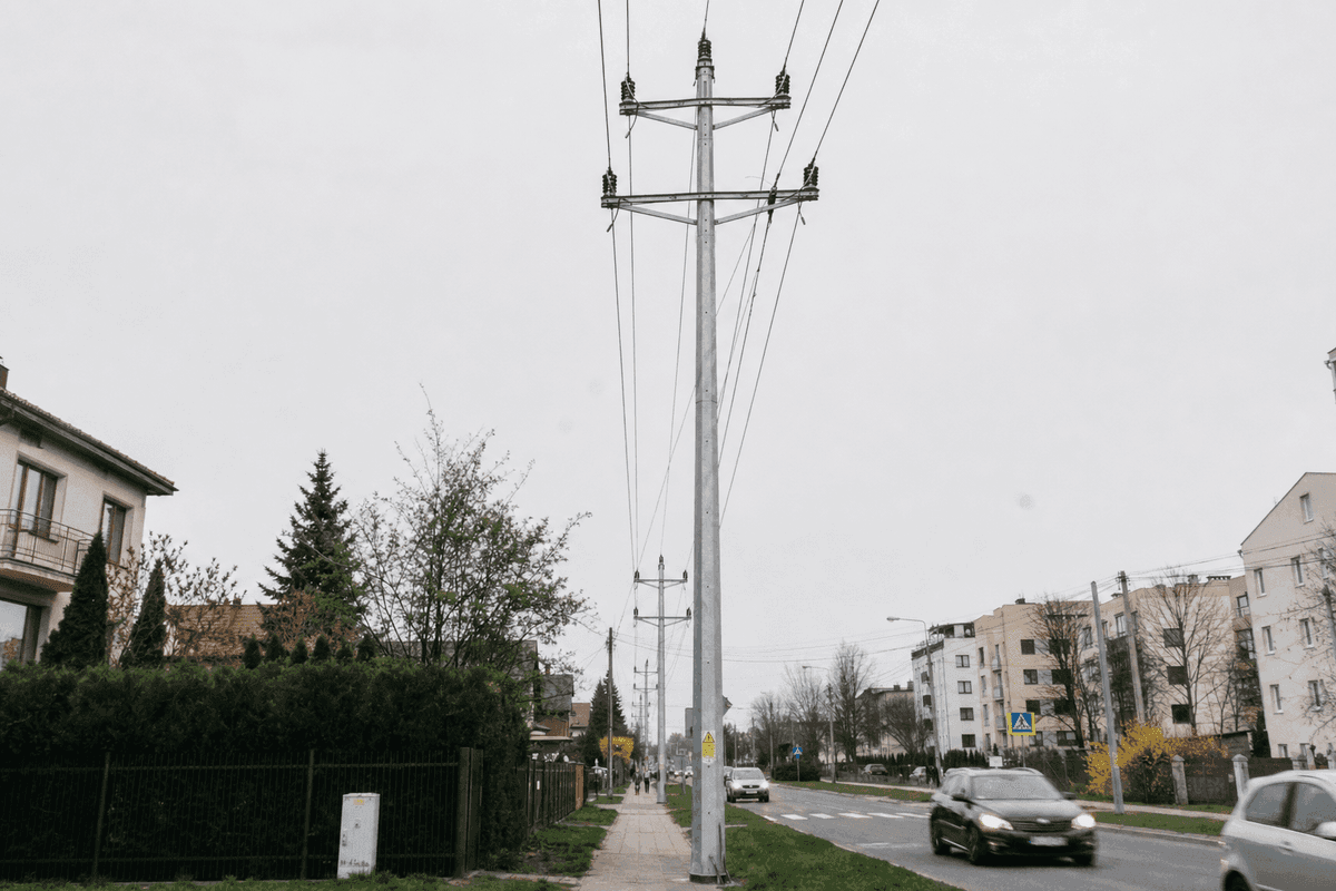
Warsaw Power Transmission Tower Market Analysis: 0.4kV Steel Tubular Pole Configuration Guide
Summary
Warsaw’s peri-urban and community distribution corridors can suit a typical 0.4kV overhead build using approximately 425 steel tubular poles at 12m height, 50m span, and about 21km line length. Based on a 30m/s wind class and GB 50061-aligned low-voltage design, this configuration fits rural-edge and utility extension needs.
Key Takeaways
A Warsaw-area low-voltage distribution build of this profile would typically use approximately 425 units of 12m tapered steel tubular poles over about 21km at a 50m average span.
- The recommended class is 0.4kV low-voltage single circuit, using 12m poles with about 2t/pole deadweight and 200kg/m section mass.
- For this configuration, conductor selection is ACSR 50, with about 200kg/km mass and 16kN maximum tension for short-span community feeders.
- Pole geometry suits phase spacing of 0.4m and ground clearance of 4.5m, which aligns with low-voltage rural and community distribution practice.
- The specified wind basis is Class 2 at 30m/s, which is relevant for Warsaw’s winter storm and open-corridor exposure conditions.
- A typical line of 21km at 50m span mathematically supports roughly 420-425 poles, allowing for angle, terminal, and road-crossing structures.
- Pole material is hot-dip galvanized Q345 steel, with a concrete base foundation, grounding set, cross arm, insulator pin, and climbing pegs.
- The design life is 25 years, and applicable standards for this low-voltage profile are GB 50061 (≤10kV overhead distribution) and IEC 60865.
- For Warsaw procurement planning, SOLAR TODO would typically position this product as a steel monopole alternative to bulkier concrete or wood options in constrained access corridors.
Market Context for Warsaw
Warsaw is Poland’s largest city, with 1.86 million residents in the city proper and a metropolitan population above 3 million, creating steady pressure on medium- and low-voltage distribution at the urban edge, logistics zones, and expanding residential communities. According to Statistics Poland (2024), Warsaw remains the country’s largest municipal load center by population and business concentration. According to the City of Warsaw strategy documents, metropolitan growth continues in outer districts where distribution reinforcement and infill connections are recurring utility tasks.
Climate and wind conditions also matter for pole selection. According to Climate-Data.org and IMGW-PIB reference climate datasets, Warsaw sees cold winters, seasonal icing risk, and year-round exposure to wind events that can affect overhead line loading. For short-span 0.4kV feeders, a 30m/s wind basis is a practical design point for community and rural-edge applications where open land, road verges, and low-rise development create uneven exposure.
Poland’s power system is transmission-heavy at the national level, but local service quality depends on distribution reinforcement closer to end users. According to the International Energy Agency (IEA) (2023), Poland continues grid modernization to support electrification, reliability, and distributed energy integration. According to the World Bank (2022), distribution network quality and resilience remain central to economic productivity in fast-growing urban regions.
For Warsaw specifically, the relevant use case here is not 110kV or 220kV transmission steelwork. It is a lower-voltage feeder and service-extension profile. That distinction is important because the correct engineering class for 0.4kV is a 12m pole, not a tall sub-transmission or transmission structure. SOLAR TODO should therefore be assessed in the context of low-voltage distribution extensions, community electrification links, and utility replacement programs rather than bulk transmission corridors.
As IEC states, "the design of overhead lines shall take into account climatic, mechanical and electrical loading conditions" (IEC 60826). ENTSO-E also notes that distribution resilience increasingly depends on local reinforcement and asset condition rather than only upstream transmission capacity. Those two points fit Warsaw’s mixed urban-peri-urban grid reality.
Recommended Technical Configuration
For Warsaw’s peri-urban 0.4kV feeder extensions, a typical build would use approximately 425 galvanized 12m steel tubular poles over 21km, with ACSR 50 conductor, 50m spans, and concrete base foundations.
The project-specific configuration supplied for this article is a low-voltage rural/community distribution class, and that is the correct fit for Warsaw fringe districts, municipal service roads, light industrial plots, and village-style settlements within the wider Mazovian development belt. A typical 425-unit deployment of this scale would consist of 12m tapered steel tubular poles in single-circuit 0.4kV arrangement. Total route length would be about 21km at an average 50m span.
This is intentionally below the standard 10-35kV distribution table row because the use case is 0.4kV low-voltage service distribution. The supplied design still aligns with the broader low-height distribution logic: short spans, modest conductor tension, and lower attachment geometry. It should not be described as a 35kV line, and it should not borrow 66-110kV or 220kV pole heights. In Warsaw, that matters because utility buyers will immediately reject a low-voltage design presented with 24m or 40m structures.
A tapered steel tubular pole is well suited where right-of-way is narrow, where visual bulk matters, or where transport and handling need to stay simpler than lattice alternatives. Compared with broad-footprint structures, a single steel pole with flange-connected sections and a concrete base foundation can reduce obstruction at road shoulders and settlement entrances. For municipal and utility planners, this can help where Warsaw’s suburban streets, drainage ditches, and mixed-use parcels leave limited room for wider structures.
The recommended electrical set is straightforward: ACSR 50 conductor, 0.4m phase spacing, 0.1m insulator length, and 4.5m ground clearance. That combination suits short-span LV distribution with moderate mechanical loading. SOLAR TODO can position this as a practical option for utilities or EPC contractors seeking repeatable steel pole packages with standardized accessories and galvanizing quality.
For buyers comparing alternatives, the main decision points are route density, corrosion resistance, handling logistics, and maintenance cycle. Hot-dip galvanized Q345 steel gives predictable fabrication and coating performance. According to ISO 1461 guidance on galvanized coatings, zinc protection remains a standard route to long-term atmospheric corrosion control for outdoor steel assets. In Warsaw’s freeze-thaw and wet-season environment, that is more relevant than cosmetic finish.
Technical Specifications
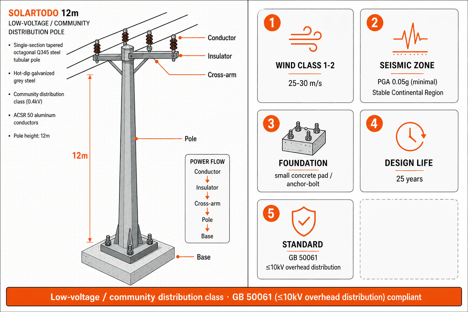
This Warsaw-oriented low-voltage configuration centers on a 12m, 0.4kV, single-circuit galvanized steel tubular pole with approximately 2t unit weight, 50m span, and 25-year design life.
- Product type: Steel tubular Power Transmission Tower for low-voltage overhead distribution
- Pole form: 12m tapered steel tubular pole
- Voltage class: 0.4kV low-voltage distribution, single circuit
- Quantity basis: Approximately 425 units for a typical 21km route
- Pole weight: ~2t/pole
- Linear steel mass: ~200kg/m
- Material: Hot-dip galvanized Q345 steel
- Conductor: ACSR 50
- Conductor mass: ~200kg/km
- Maximum conductor tension: 16kN
- Average span: 50m
- Phase spacing: 0.4m
- Ground clearance: 4.5m
- Insulator length: 0.1m
- Wind class: Class 2, 30m/s
- Foundation type: Concrete base foundation
- Accessories: Climbing pegs, cross arm, grounding set, insulator pin
- Design life: 25 years
- Pole class: Low-voltage rural / community distribution
- Applicable standards: GB 50061 (≤10kV overhead distribution), IEC 60865
For context, this specification is below the 10-35kV distribution class used for higher-voltage feeders, which typically falls in the 12-18m and 1-3t/pole range. The supplied 12m and ~2t/pole values are therefore technically coherent for a 0.4kV line. According to IEC (2019), short-circuit and mechanical force coordination should be verified at the system design stage, especially at angle poles, dead ends, and road crossings.
Implementation Approach
A typical Warsaw-area rollout would proceed in 5 phases over roughly 4-8 months for 21km, depending on permits, winter civil works constraints, and utility outage windows.
Phase 1 is route survey and loading verification. This usually includes topographic review, soil checks at representative locations, crossing identification, and confirmation of span distribution around the nominal 50m design. In peri-urban Warsaw, that step should also map drainage channels, road setbacks, and underground utility conflicts. For a 21km route, desktop and field validation commonly take 3-6 weeks.
Phase 2 is detailed design and procurement. Pole schedules, anchor details, conductor sag-tension checks, and accessory lists are finalized at this stage. For 425 poles, buyers normally split the bill of materials into poles, foundations, conductors, insulators, and earthing kits to simplify tender comparison. SOLAR TODO can support this stage through product data sheets and fabrication documentation via the product page or direct technical coordination through contact us.
Phase 3 is manufacturing and logistics. Hot-dip galvanized Q345 poles are fabricated, drilled, flanged if sectionalized, and packed for container or break-bulk shipment. A 425-unit order requires close attention to bundle sequencing so erection crews receive tangent, angle, and terminal structures in the correct order. Depending on shipping mode and customs handling into Poland, this stage often takes 8-12 weeks.
Phase 4 is civil work and erection. Concrete base foundations are cast first, then poles are erected after strength gain. With standard access and moderate soil conditions, a contractor may complete 8-15 pole foundations per day and erect 6-12 poles per day with a small crane crew. Winter freeze conditions around Warsaw can slow excavation and curing, so schedule buffers are prudent between November and March.
Phase 5 is stringing, grounding, testing, and energization. ACSR 50 conductor is strung, sagged, clipped, and checked against the 4.5m ground clearance requirement. Grounding continuity, hardware torque, and visual galvanizing inspection are completed before energization. According to IEEE guidance on overhead line asset management, early inspection after commissioning reduces defect carryover into the first operating year.
Expected Performance & ROI
For a 21km, 425-pole Warsaw low-voltage line, the main return comes from lower outage exposure, lower replacement frequency than wood, and predictable 25-year asset life rather than from energy generation metrics.
For this product type, ROI should be assessed as a network-asset decision. The relevant measures are lifecycle maintenance, corrosion resistance, structural consistency, and service continuity. A galvanized steel tubular pole generally offers more uniform geometry than timber and a smaller footprint than many concrete alternatives. In Warsaw’s wet-freeze climate, that can reduce inspection and replacement uncertainty over a 25-year horizon.
According to the World Bank (2022), power reliability improvements have direct productivity value for commercial and residential users. According to the IEA (2023), distribution investment is increasingly justified by resilience and electrification demand rather than only by load growth. For a utility or EPC contractor, that means the business case can be framed around avoided outages, reduced emergency replacement events, and lower corridor maintenance frequency.
A practical payback estimate for steel-vs-legacy replacement depends on local fault history, vegetation exposure, and crew costs. In many distribution settings, utilities evaluate payback over 5-12 years when reduced failure rates and lower maintenance truck rolls are included. That is not a universal number, but it is a reasonable benchmark range for screening. Warsaw buyers should run a net present value model using local labor rates, outage penalties, and expected replacement cycles.
Maintenance demand is usually moderate. Visual inspection is commonly annual, with detailed hardware and grounding checks every 3-5 years, and targeted recoating or hardware replacement only where coating damage or corrosion is localized. ISO and IEC guidance both support condition-based maintenance over purely time-based replacement where coating integrity remains intact. For SOLAR TODO, this is an important procurement message: steel tubular poles are purchased as long-life infrastructure, not as short-cycle consumables.
Results and Impact
A Warsaw utility using this 0.4kV configuration could expect a 21km community feeder with 425 poles, 50m spans, and a 25-year design basis that supports stable expansion at the city edge.
The likely impact is practical rather than dramatic. First, the configuration supports orderly extension of low-voltage service into new residential clusters, municipal utility loads, and light commercial plots. Second, the 12m steel pole profile keeps the structure proportional to the electrical duty, avoiding the cost and visual burden of taller sub-transmission supports. Third, the Q345 hot-dip galvanized build can improve asset consistency across a long route of 21km.
For Warsaw planners, the strongest fit is where access roads are narrow, rights-of-way are fragmented, or utilities want standardized steel components that can be repeated across multiple feeder branches. If the route later requires selective reinforcement, angle or terminal poles can be upgraded locally without redesigning the whole corridor. That modularity is often more useful at 0.4kV than a one-size-fits-all structure strategy.
Comparison Table
For Warsaw low-voltage distribution, a 12m steel tubular pole is usually the best fit when compared against over-sized MV/HV structures or bulkier support types.
| Parameter | Recommended Warsaw LV Configuration | 10-35kV Distribution Class Reference | 66-110kV Class Reference |
|---|---|---|---|
| Voltage | 0.4kV | 10-35kV | 66-110kV |
| Pole height | 12m | 12-18m | 18-30m |
| Pole weight | ~2t/pole | 1-3t/pole | 5-15t/pole |
| Circuit | Single circuit | Single or double | Single or double |
| Typical span | 50m | 80-150m | 200-300m |
| Poles per km | ~20 poles/km | 8-12 poles/km | 4-5 poles/km |
| Conductor | ACSR 50 | ACSR family by load | ACSR family by load |
| Wind basis | 30m/s | Project-specific | Project-specific |
| Foundation | Concrete base | Concrete/anchor cage | Concrete/anchor cage |
| Best use case | Community / rural LV | MV distribution feeders | Sub-transmission |
The table shows why Warsaw buyers should not overspecify this application. A 0.4kV route with 50m spans needs more poles per kilometer than a 10-35kV feeder, but each structure is materially smaller and simpler. That usually improves handling and route flexibility where settlement density changes quickly.
Pricing & Quotation
SOLAR TODO offers three pricing tiers for this product line: FOB Supply (equipment ex-works China), CIF Delivered (including ocean freight and insurance), and EPC Turnkey (fully installed, commissioned, with 1-year warranty). Volume discounts are available for large-scale deployments. Configure your system online for an instant estimate, or request a custom quotation from our engineering team at [email protected].
Frequently Asked Questions
This FAQ answers the most common Warsaw buyer questions on 0.4kV steel tubular pole sizing, installation, maintenance, quotation scope, and lifecycle economics for a 425-pole profile.
Q1: What is the recommended pole type for this Warsaw application?
For the supplied use case, the correct recommendation is a 12m tapered steel tubular pole for 0.4kV low-voltage single-circuit distribution. The specified unit weight is about 2t/pole, with Q345 hot-dip galvanized steel, 50m span, and a concrete base foundation. This is a low-voltage community distribution solution, not a medium-voltage or transmission structure.
Q2: Why not use a taller 18m to 30m pole in Warsaw?
That would be over-specified for 0.4kV duty. Taller 18-30m poles belong to the 66-110kV class, with much higher structural demand and cost. For this profile, 12m is the correct height because the line uses 50m spans, 4.5m clearance, and 0.4m phase spacing, which do not require sub-transmission geometry.
Q3: How many poles are typically needed for a 21km route?
At a nominal 50m span, a 21km line mathematically points to about 420 poles, and the specified design basis uses approximately 425 units. The extra quantity typically covers terminal poles, angle locations, crossings, and route deviations. Final counts depend on the surveyed alignment, not only on straight-line distance.
Q4: What conductor is matched to this configuration?
The supplied conductor is ACSR 50, with about 200kg/km mass and 16kN maximum tension. That is suitable for short-span low-voltage overhead distribution where mechanical loading remains moderate. Final sag-tension checks should still be completed for local temperature range, crossing points, and any special angle structures.
Q5: How long would installation usually take in Poland?
For a 425-pole, 21km line, a practical program is often 4-8 months from design release to energization. Manufacturing and shipping can take 8-12 weeks, while civil works and erection depend on weather, permits, and utility access windows. Winter excavation in Warsaw can extend the foundation stage if soils are frozen.
Q6: What maintenance should buyers expect over 25 years?
Routine maintenance is usually limited to annual visual inspection, hardware tightening checks, grounding verification, and localized treatment if galvanizing is damaged. A more detailed condition review every 3-5 years is common. Because the poles are hot-dip galvanized Q345 steel, the main maintenance focus is connection hardware and any site-specific corrosion points.
Q7: How does steel tubular construction compare with wood or concrete poles?
Steel tubular poles usually provide tighter dimensional consistency than wood and a smaller footprint than many concrete options. For Warsaw edge zones with constrained access, that can simplify handling and corridor use. Concrete may suit some utility standards, but steel is often preferred where transport, repeatability, and standardized accessories matter across hundreds of poles.
Q8: What is the expected ROI or payback period?
There is no single universal payback number, but utilities often screen steel pole replacement over 5-12 years when avoided failures, fewer emergency callouts, and lower replacement rates are included. The full business case should use local outage cost, labor rates, corrosion exposure, and expected service life. The design life here is 25 years.
Q9: Does SOLAR TODO provide EPC pricing or supply-only quotations?
Yes. SOLAR TODO offers FOB Supply, CIF Delivered, and EPC Turnkey quotation structures. Buyers can request a supply-only package for utility or contractor installation, or a broader scope including installation and commissioning. Quotations should clearly separate poles, foundations, conductors, accessories, logistics, and local civil exclusions.
Q10: What warranty terms are typical for this product line?
The pricing section specifies EPC Turnkey with a 1-year warranty. Buyers should also request documentation on galvanizing thickness, steel grade certification, and accessory compliance at quotation stage. For long-life steel assets, material certificates and inspection records are often as important as the warranty duration itself.
References
- Statistics Poland (2024): Warsaw population and metropolitan demographic data used to frame utility demand in Poland’s largest urban center.
- City of Warsaw (Strategy documents, 2030/2040): Municipal development and outer-district growth context relevant to peri-urban utility extension planning.
- International Energy Agency (IEA) (2023): Poland energy and grid modernization context; distribution investment supports resilience and electrification.
- World Bank (2022): Power reliability and infrastructure quality remain material to economic productivity and service continuity.
- IEC (2019): IEC 60865 mechanical effects and force considerations for short-circuit conditions in electrical installations.
- IEC (2019): IEC 60826 design criteria for overhead transmission lines, including climatic and mechanical loading principles.
- ISO (2019): ISO 1461 hot-dip galvanized coatings on fabricated iron and steel articles; coating quality and corrosion protection basis.
- ENTSO-E (2022): European grid resilience and network planning context, including the importance of local reinforcement and system reliability.
Equipment Deployed
- 425 × 12m tapered steel tubular pole, 0.4kV single-circuit, ~2t/pole
- Hot-dip galvanized Q345 steel pole body, ~200kg/m
- ACSR 50 conductor, ~200kg/km, max tension 16kN
- Cross arm assembly for low-voltage single-circuit distribution
- Insulator pin set with 0.1m insulator length
- Grounding set for each pole location
- Climbing pegs for maintenance access
- Concrete base foundation system
- Phase spacing configuration: 0.4m
- Ground clearance design: 4.5m
- Wind class 2 structural basis: 30m/s
- Design life basis: 25 years