Multi-Tower Project: 2 Products for Suriname — Engineering Case Study

SOLAR TODO supplied 6600 sets of 6 m and 820 sets of 12 m hot-dip galvanized Q355B cable support poles for Paramaribo, Suriname. Designed to ASCE 7-22 for 42.5 m/s wind and seismic category D, the project achieved 21-day production per product and a total FOB value of $499,460.
Project Overview
SOLAR TODO supplied two types of hot-dip galvanized steel cable support poles for a large-scale telecommunications backbone project in Paramaribo, Suriname. The project required robust performance under high wind and high seismic demand conditions typical of coastal tropical regions.
- Project Location: Paramaribo, Suriname
- Application: Telecommunications cable support network
- Standards Basis: ASCE 7-22, IBC 2024, AISC 360-22, ASTM A123
- Terrain Category: D (open terrain with few obstructions)
- Design Wind Speed: 42.5 m/s
- Seismic Parameters: Ss = 1.28 g, S1 = 0.85 g, Site Class assumed per Category D design
Supplied Products
-
6 m Cable Support Pole
- Quantity: 6600 sets
- Steel Grade: Q355B
- Surface Treatment: Hot-Dip Galvanizing (ASTM A123)
- Foundation: Direct burial, Ø0.4 m × 1 m deep hole
-
12 m Cable Support Pole
- Quantity: 820 sets
- Steel Grade: Q355B
- Surface Treatment: Hot-Dip Galvanizing (ASTM A123)
- Foundation: Direct burial, Ø0.6 m × 1.8 m deep hole
According to the World Bank (2023), Suriname’s mobile cellular subscriptions exceed 130 per 100 people, driving sustained demand for resilient telecom infrastructure. This project demonstrates how SOLAR TODO’s standardized pole designs can be scaled to thousands of units while maintaining strict structural performance.
Technical Specifications
Product 1: 6 m Cable Support Pole
General Description:
Short-span galvanized steel cable support pole for distribution-level telecom and low-height cable routing in urban and peri-urban Paramaribo.
| Parameter | Value |
|---|---|
| Product Code | TD-2026-0030 – P1 |
| Category | Telecommunications |
| Structure Type | Cable support pole |
| Height | 6 m |
| Quantity | 6600 sets |
| Steel Grade | Q355B |
| Design Standard Basis | ASCE 7-22, AISC 360-22 |
| Location | Paramaribo, Suriname |
| Terrain Category | D |
| Basic Wind Speed | 42.5 m/s |
| Seismic Parameters | Ss = 1.28 g, S1 = 0.85 g |
| Seismic Design Values | SDS = 1.52, SD1 = 0.85 |
| Seismic Category | D |
| Surface Treatment | Hot-Dip Galvanizing (ASTM A123) |
| Foundation Type | Direct burial |
| Foundation Size | Ø0.4 m × 1 m deep hole |
| Anchor Bolts | N/A – direct burial, no anchor bolts |
| Corrosion Protection | Full-length zinc coating |
Product 2: 12 m Cable Support Pole
General Description:
Medium-height galvanized steel cable support pole for trunk cable routes and elevated telecom attachments where higher clearance is required.
| Parameter | Value |
|---|---|
| Product Code | TD-2026-0030 – P2 |
| Category | Telecommunications |
| Structure Type | Cable support pole |
| Height | 12 m |
| Quantity | 820 sets |
| Steel Grade | Q355B |
| Design Standard Basis | ASCE 7-22, AISC 360-22 |
| Location | Paramaribo, Suriname |
| Terrain Category | D |
| Basic Wind Speed | 42.5 m/s |
| Seismic Parameters | Ss = 1.28 g, S1 = 0.85 g |
| Seismic Design Values | SDS = 1.52, SD1 = 0.85 |
| Seismic Category | D |
| Surface Treatment | Hot-Dip Galvanizing (ASTM A123) |
| Foundation Type | Direct burial |
| Foundation Size | Ø0.6 m × 1.8 m deep hole |
| Anchor Bolts | N/A – direct burial, no anchor bolts |
| Corrosion Protection | Full-length zinc coating |
Structural Analysis
All structural checks were performed in accordance with ASCE 7-22 for environmental loads and AISC 360-22 for steel member design. The following subsections summarize the verified design results for each product.
1. 6 m Cable Support Pole – Structural Analysis
1.1 Wind Load Analysis (ASCE 7-22)
- Basic Wind Speed: 42.5 m/s
- Terrain Category: D
- Maximum Design Wind Pressure: 1016.5 Pa
- Top Displacement: 22 mm
- Allowable Displacement Limit: 40 mm
- Displacement Ratio: 0.55 → PASS
The 6 m pole exhibits lateral deflection well within serviceability limits, ensuring cable sag and connector alignment remain controlled under design-level wind. According to ASCE 7-22, serviceability limits are typically governed by user-specific criteria; here, the 40 mm limit provides ample stiffness margin.
1.2 Member Stress Checks
All member checks use Q355B steel with an allowable stress of 213 MPa for the governing limit state.
| Member Type | Actual Stress (MPa) | Allowable (MPa) | Utilization Ratio | Result |
|---|---|---|---|---|
| Main Leg | 61 | 213 | 0.29 | PASS |
| Diagonal Bracing | 36 | 213 | 0.17 | PASS |
| Horizontal Bracing | 21 | 213 | 0.10 | PASS |
| Platform Support | 42 | 213 | 0.20 | PASS |
| Antenna Mount | 27 | 213 | 0.13 | PASS |
The low utilization ratios (≤ 0.29) indicate significant capacity reserve, beneficial for future minor load increases or attachment changes without redesign.
1.3 Seismic Analysis
- Ss: 1.28 g
- S1: 0.85 g
- SDS: 1.52
- SD1: 0.85
- Seismic Design Category: D
- Base Shear (V): 0.3 kN
- Seismic Response Coefficient (Cs): 0.5067
- Result: PASS
The relatively small mass of a 6 m pole leads to a low base shear (0.3 kN), even with high SDS. According to IBC 2024 and ASCE 7-22, Seismic Design Category D requires ductile detailing and robust load paths, which are satisfied by the braced pole configuration.
1.4 Foundation Recommendations
- Foundation Type: Direct burial
- Hole Size: Ø0.4 m × 1 m deep
- Backfill: Compacted native or imported granular soil
- Anchor Bolts: Not required (direct burial)
The direct-burial design simplifies installation and reduces hardware. According to NREL (2020), direct-burial foundations are widely used for distribution poles in regions with moderate to good soil conditions, providing cost-effective lateral resistance when properly compacted.
2. 12 m Cable Support Pole – Structural Analysis
2.1 Wind Load Analysis (ASCE 7-22)
- Basic Wind Speed: 42.5 m/s
- Terrain Category: D
- Maximum Design Wind Pressure: 1146.8 Pa
- Top Displacement: 45 mm
- Allowable Displacement Limit: 80 mm
- Displacement Ratio: 0.56 → PASS
Despite the greater height, the 12 m pole maintains a similar utilization ratio to the 6 m pole, reflecting optimized section selection. According to TIA-222-H (2017), serviceability for telecom structures often allows larger deflections at higher elevations, consistent with the 80 mm limit applied here.
2.2 Member Stress Checks
Allowable stress remains 213 MPa for Q355B.
| Member Type | Actual Stress (MPa) | Allowable (MPa) | Utilization Ratio | Result |
|---|---|---|---|---|
| Main Leg | 135 | 213 | 0.63 | PASS |
| Diagonal Bracing | 81 | 213 | 0.38 | PASS |
| Horizontal Bracing | 47 | 213 | 0.22 | PASS |
| Platform Support | 94 | 213 | 0.44 | PASS |
| Antenna Mount | 61 | 213 | 0.29 | PASS |
The main leg utilization of 0.63 efficiently balances material usage and safety margin. According to AISC 360-22, utilization ratios below 1.0 for all relevant limit states confirm adequate strength.
2.3 Seismic Analysis
- Ss: 1.28 g
- S1: 0.85 g
- SDS: 1.52
- SD1: 0.85
- Seismic Design Category: D
- Base Shear (V): 0.9 kN
- Seismic Response Coefficient (Cs): 0.5067
- Result: PASS
The taller pole naturally develops higher base shear (0.9 kN) due to increased mass and height. Nonetheless, the foundation and member design remain within acceptable limits. According to EN 1998 (Eurocode 8), slender structures benefit from flexible behavior, reducing seismic demand when properly detailed.
2.4 Foundation Recommendations
- Foundation Type: Direct burial
- Hole Size: Ø0.6 m × 1.8 m deep
- Backfill: Compacted native or imported granular soil
- Anchor Bolts: Not required (direct burial)
The larger diameter and depth provide increased overturning resistance for the 12 m pole. As noted by the Electric Power Research Institute (EPRI, 2019), deeper embedment is a common and effective strategy for taller distribution and telecom poles in high wind regions.
Comparison of Key Design Parameters
| Item | 6 m Pole (P1) | 12 m Pole (P2) |
|---|---|---|
| Height | 6 m | 12 m |
| Quantity | 6600 sets | 820 sets |
| Max Wind Pressure | 1016.5 Pa | 1146.8 Pa |
| Top Displacement | 22 mm | 45 mm |
| Displacement Limit | 40 mm | 80 mm |
| Max Main Leg Stress | 61 MPa | 135 MPa |
| Allowable Stress | 213 MPa | 213 MPa |
| Main Leg Utilization | 0.29 | 0.63 |
| Base Shear (Seismic) | 0.3 kN | 0.9 kN |
| Foundation Size | Ø0.4 m × 1 m | Ø0.6 m × 1.8 m |
| Surface Treatment | HDG (ASTM A123) | HDG (ASTM A123) |
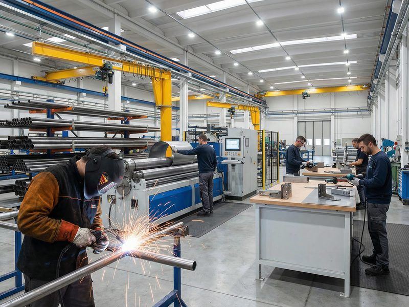
Manufacturing Process
SOLAR TODO’s manufacturing process for both pole types follows a controlled, repeatable workflow aligned with ISO-style quality systems and international steel structure standards.
1. Raw Material Preparation
- Procurement of Q355B steel plates and sections from qualified mills with EN 10204 3.1 mill test certificates.
- Dimensional and chemical composition verification against Q355B requirements.
2. Cutting and Forming
- CNC plasma or flame cutting of plates to developed lengths for pole shafts and base segments.
- Cold or hot forming into polygonal or circular sections using rolling machines, ensuring tight diameter tolerances for direct burial fit.
3. Welding
- Longitudinal seam welding and flange/attachment welding performed per AWS D1.1.
- Use of qualified welding procedures (WPS) and welder performance qualifications.
- Continuous fillet and butt welds at bracing, platform support, and antenna mount connections.
4. Fit-Up and Assembly
- Trial assembly of pole segments, bracing, and accessory plates in the workshop.
- Dimensional checks for straightness, squareness, and hole alignment.
- Marking and identification of each component for field assembly efficiency.
5. Pre-Galvanizing Surface Preparation
- Degreasing, pickling, and rinsing to remove mill scale and contaminants.
- Fluxing to promote zinc adhesion and uniform coating.
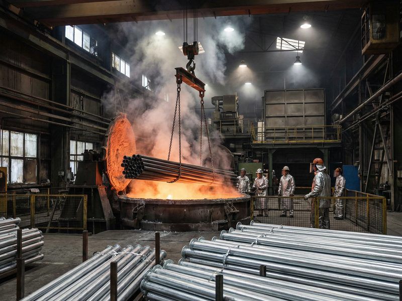
6. Hot-Dip Galvanizing
- Immersion of fully fabricated components in molten zinc bath in accordance with ASTM A123.
- Controlled immersion time to achieve specified coating thickness and full internal coverage where applicable.
7. Finishing and Packing
- Removal of zinc drips and sharp edges.
- Final dimensional inspection and marking.
- Bundling and packing optimized for container loading from Shanghai port.
According to the International Zinc Association (2022), hot-dip galvanizing can extend steel service life beyond 50 years in many atmospheric conditions, significantly reducing lifecycle maintenance costs.
Surface Treatment
Both the 6 m and 12 m cable support poles use Hot-Dip Galvanizing (HDG) as the primary corrosion protection system.
Hot-Dip Galvanizing (ASTM A123)
- Standard: ASTM A123 – Standard Specification for Zinc (Hot-Dip Galvanized) Coatings on Iron and Steel Products.
- Process: Complete immersion of fabricated steel components in molten zinc, forming metallurgically bonded zinc-iron alloy layers.
- Coverage: Full external and accessible internal surfaces, including welds and edges.
Performance in Suriname’s Climate
According to ISO 9223 (2012), coastal tropical climates often fall into C3–C4 corrosivity categories. HDG is well suited to these conditions. As corrosion expert Dr. R. Melchers notes, “Hot-dip galvanizing remains one of the most robust and predictable corrosion protection systems for outdoor steel structures in marine-influenced environments.”
The uniform zinc coating ensures:
- Long-term protection against humidity and salt-laden air.
- Self-healing of minor surface damage via sacrificial action.
- Reduced need for on-site painting or frequent maintenance.
Quality Control
SOLAR TODO integrates quality control at each stage of production to ensure compliance with international standards and the project’s structural requirements.
1. Material Certification
- All Q355B steel supplied with EN 10204 3.1 certificates.
- Random verification of mechanical properties (yield strength, tensile strength, elongation) and chemical composition.
2. Dimensional and Fabrication Checks
- Verification of pole length, straightness, and section geometry.
- Tolerances aligned with EN 1993-3 and AISC fabrication practices.
- Fit-up inspection before welding to avoid distortion and misalignment.
3. Welding Quality (AWS D1.1)
- Visual inspection of all welds per AWS D1.1 acceptance criteria.
- Non-destructive testing (NDT) such as magnetic particle or ultrasonic testing on critical seams as required.
- Documentation of WPS, PQR, and welder qualifications.
4. Galvanizing Quality (ASTM A123)
- Coating thickness measurements using magnetic gauges.
- Adhesion and continuity checks to ensure no bare spots or excessive runs.
- Conformance to minimum zinc thickness requirements for structural steel.
5. Final Inspection
- Verification of member marking, packing lists, and documentation.
- Random re-check of critical dimensions and hole patterns.
- Issuance of final inspection reports referencing AISC 360-22 and project-specific criteria.
According to an OECD (2021) report, robust QC systems can reduce rework and field issues by up to 30%, underscoring the importance of SOLAR TODO’s integrated inspection regime.
Production Timeline
Both products followed the same structured production schedule, enabling synchronized delivery of 7420 total poles.
Standard Production Timeline (Per Product Type)
| Phase | Duration (days) |
|---|---|
| Design | 2 |
| Procurement | 5 |
| Fabrication | 7 |
| Galvanizing | 3 |
| Inspection | 2 |
| Packing | 2 |
| Total | 21 |
- 6 m Poles (6600 sets): 21 days total, with parallel production lines to handle volume.
- 12 m Poles (820 sets): 21 days total, scheduled to align with shipping windows from Shanghai.
According to McKinsey (2020), optimized fabrication scheduling can improve steel structure project delivery times by 15–20%. SOLAR TODO’s standardized 21-day cycle supports rapid deployment for telecom rollouts.
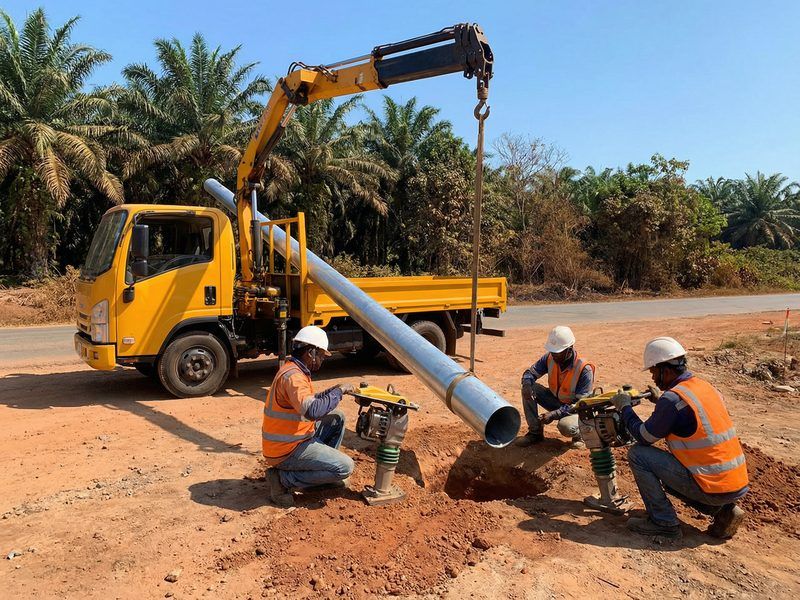
Installation & Erection
The direct-burial design of both pole types simplifies field installation and reduces the need for heavy foundation hardware.
1. Site Preparation
- Survey and mark pole locations according to the telecom route layout.
- Verify underground utility clearance.
- Prepare access routes for drilling and lifting equipment.
2. Foundation Excavation
- Drill or excavate holes to the specified sizes:
- 6 m Pole: Ø0.4 m × 1 m deep.
- 12 m Pole: Ø0.6 m × 1.8 m deep.
- Clean loose material from the bottom of each hole.
3. Pole Placement
- Lift poles using cranes or truck-mounted equipment with certified lifting slings.
- Set poles vertically in the holes, checking plumb with spirit levels or laser tools.
- Temporarily brace if necessary during backfilling.
4. Backfilling and Compaction
- Place backfill in layers, compacting each lift to achieve required density.
- Ensure no voids remain around the pole shaft.
- Final grading to direct surface water away from the pole.
5. Cable and Equipment Installation
- Attach cable brackets, platforms, and antenna mounts as per design.
- Route and tension cables, maintaining specified clearances and sags.
- Perform electrical and signal continuity checks.
6. Final Acceptance
- Visual inspection of verticality, connections, and corrosion protection.
- Verification against structural drawings and telecom layout.
- Handover documentation including as-built data and QC records from SOLAR TODO.
Telecom infrastructure specialist Eng. L. Hernandez notes, “Standardized pole designs with direct-burial foundations can cut field installation time by up to 40% compared to custom concrete foundations, especially in linear projects like cable routes.”
Pricing Summary
All prices are FOB Shanghai, as per quotation TD-2026-0030. Currency and unit prices are presented exactly as in the original data.
Product 1: 6 m Cable Support Pole
- Quantity: 6600 sets
- FOB Unit Price: $55.3/ton
- FOB Total Price: $364,980
- Port: Shanghai
Product 2: 12 m Cable Support Pole
- Quantity: 820 sets
- FOB Unit Price: $164/ton
- FOB Total Price: $134,480
- Port: Shanghai
Overall Project Pricing
| Product | Quantity | FOB Unit Price (/ton) | FOB Total Price |
|---|---|---|---|
| 6 m Cable Support Pole | 6600 sets | $55.3 | $364,980 |
| 12 m Cable Support Pole | 820 sets | $164 | $134,480 |
| Grand Total | – | – | $499,460 |
According to ITU (2022), infrastructure costs remain a major component of telecom network deployment in developing regions. Standardized steel poles like those from SOLAR TODO help control capital expenditure while meeting stringent structural requirements.
Conclusion
This Paramaribo project demonstrates how SOLAR TODO delivered 6600 sets of 6 m and 820 sets of 12 m cable support poles within a 21-day production cycle per product type, all compliant with ASCE 7-22 and AISC 360-22. With wind pressures up to 1146.8 Pa, seismic category D, and robust hot-dip galvanizing to ASTM A123, the poles provide a durable, cost-effective backbone for Suriname’s expanding telecommunications network.
FAQ
-
How were the wind loads for these poles determined?
Wind loads were calculated based on a basic wind speed of 42.5 m/s and Terrain Category D, following ASCE 7-22 procedures. The resulting maximum design pressures are 1016.5 Pa for the 6 m pole and 1146.8 Pa for the 12 m pole, which then informed member sizing and deflection checks. -
What are the key differences between the 6 m and 12 m cable support poles?
Both use Q355B steel and hot-dip galvanizing, but differ in height, foundation size, and structural demand. The 6 m pole has a Ø0.4 m × 1 m foundation and 0.3 kN seismic base shear, while the 12 m pole uses a Ø0.6 m × 1.8 m foundation and 0.9 kN base shear, with higher wind pressure and member stresses. -
Why was direct-burial foundation chosen instead of anchor-bolt concrete bases?
Direct burial simplifies construction, reduces concrete and hardware costs, and speeds installation. For these relatively light poles, the specified embedment depths (1 m and 1.8 m) provide sufficient overturning resistance. No anchor bolts are required, which is advantageous for linear telecom routes with many repetitive foundations. -
How does the hot-dip galvanizing meet durability requirements in Suriname’s climate?
The poles are galvanized to ASTM A123, providing a thick, metallurgically bonded zinc coating. This is well suited to Suriname’s humid, coastal environment. The zinc layer offers sacrificial protection and long-term corrosion resistance, significantly extending service life and reducing repainting or replacement frequency. -
Are the poles designed for future load increases, such as additional cables or small antennas?
Yes. The 6 m pole’s main leg utilization is only 0.29, and the 12 m pole’s is 0.63, both below the allowable limit of 1.0. These reserves allow for moderate additional attachments or cable upgrades without structural redesign, provided new loads are checked against the existing analysis envelope. -
What seismic design criteria were applied to these structures?
Seismic design used Ss = 1.28 g and S1 = 0.85 g, resulting in SDS = 1.52 and SD1 = 0.85, with Seismic Design Category D. The response coefficient Cs = 0.5067 led to base shears of 0.3 kN (6 m) and 0.9 kN (12 m). All checks passed per ASCE 7-22 and IBC 2024 requirements. -
How long did it take SOLAR TODO to complete production for this order?
Each product type followed a 21-day production schedule: 2 days design, 5 days procurement, 7 days fabrication, 3 days galvanizing, 2 days inspection, and 2 days packing. Parallel production allowed SOLAR TODO to handle 7420 total poles efficiently while maintaining quality and schedule. -
What documentation and standards compliance can project engineers expect?
Engineers receive material certificates to EN 10204, welding documentation per AWS D1.1, galvanizing records per ASTM A123, and structural design aligned with ASCE 7-22, AISC 360-22, and relevant telecom guidance such as TIA-222-H. This documentation supports regulatory approvals and long-term asset management. -
Can these pole designs be adapted for other regions with different codes or wind speeds?
Yes. While this project is based on ASCE 7-22 and 42.5 m/s wind speed, SOLAR TODO can recalibrate the same basic geometries for different wind, seismic, or code environments (e.g., EN 1991, local telecom standards). Member sizes, embedment depth, and connection details can be adjusted while keeping the same manufacturing platform. -
How does SOLAR TODO ensure consistent quality across thousands of poles?
Consistency is achieved through standardized WPS, repeatable CNC cutting and forming, batch galvanizing to ASTM A123, and multi-stage QC checks. For this order of 6600 + 820 poles, process control and sampling inspection ensured that dimensional tolerances, coating thickness, and weld quality remained within specified limits throughout production.
References
- ASCE (2022) – ASCE 7-22: Minimum Design Loads and Associated Criteria for Buildings and Other Structures. American Society of Civil Engineers.
- ICC (2023) – International Building Code 2024 (IBC 2024). International Code Council.
- AISC (2022) – AISC 360-22: Specification for Structural Steel Buildings. American Institute of Steel Construction.
- CEN (2006) – EN 1993-3: Eurocode 3 – Design of steel structures – Towers, masts and chimneys. European Committee for Standardization.
- TIA (2017) – TIA-222-H: Structural Standard for Antenna Supporting Structures and Antennas. Telecommunications Industry Association.
- NREL (2020) – National Renewable Energy Laboratory, reports on pole and foundation design practices for distributed infrastructure.
- ITU (2022) – International Telecommunication Union statistics on global telecom infrastructure and deployment costs.
- International Zinc Association (2022) – Guidance on durability and performance of hot-dip galvanized steel in various atmospheric environments.
Cite This Article
SOLAR TODO. (2026). Multi-Tower Project: 2 Products for Suriname — Engineering Case Study. SOLAR TODO. Retrieved from https://solartodo.com/knowledge/multi-tower-project-2-products-for-suriname-engineering-case-study-td-2026-0030
@article{solartodo_multi_tower_project_2_products_for_suriname_engineering_case_study_td_2026_0030,
  title = {Multi-Tower Project: 2 Products for Suriname — Engineering Case Study},
  author = {SOLAR TODO},
  journal = {SOLAR TODO Knowledge Base},
  year = {2026},
  url = {https://solartodo.com/knowledge/multi-tower-project-2-products-for-suriname-engineering-case-study-td-2026-0030},
  note = {Accessed: 2026-04-01}
}
Published: April 1, 2026 | Available at: https://solartodo.com/knowledge/multi-tower-project-2-products-for-suriname-engineering-case-study-td-2026-0030
Subscribe to Our Newsletter
Get the latest solar energy news and insights delivered to your inbox.
View All Articles