Lima Power Transmission Tower Market Analysis: 35kV Double-Circuit Configuration Guide
Summary
Lima's 35kV municipal distribution profile can fit an approximately 225-pole, 18km double-circuit steel tubular line using 25m Q345 monopoles, 80m spans, ACSR-70 conductors, and 30m/s wind design for coastal corrosion exposure.
Key Takeaways
For Lima's 35kV corridor profile, the recommended technical baseline is approximately 225 units across 18km with 25m galvanized steel tubular poles.
- A typical 225-unit deployment would support about 18km of 35kV double-circuit municipal distribution at 80m average span.
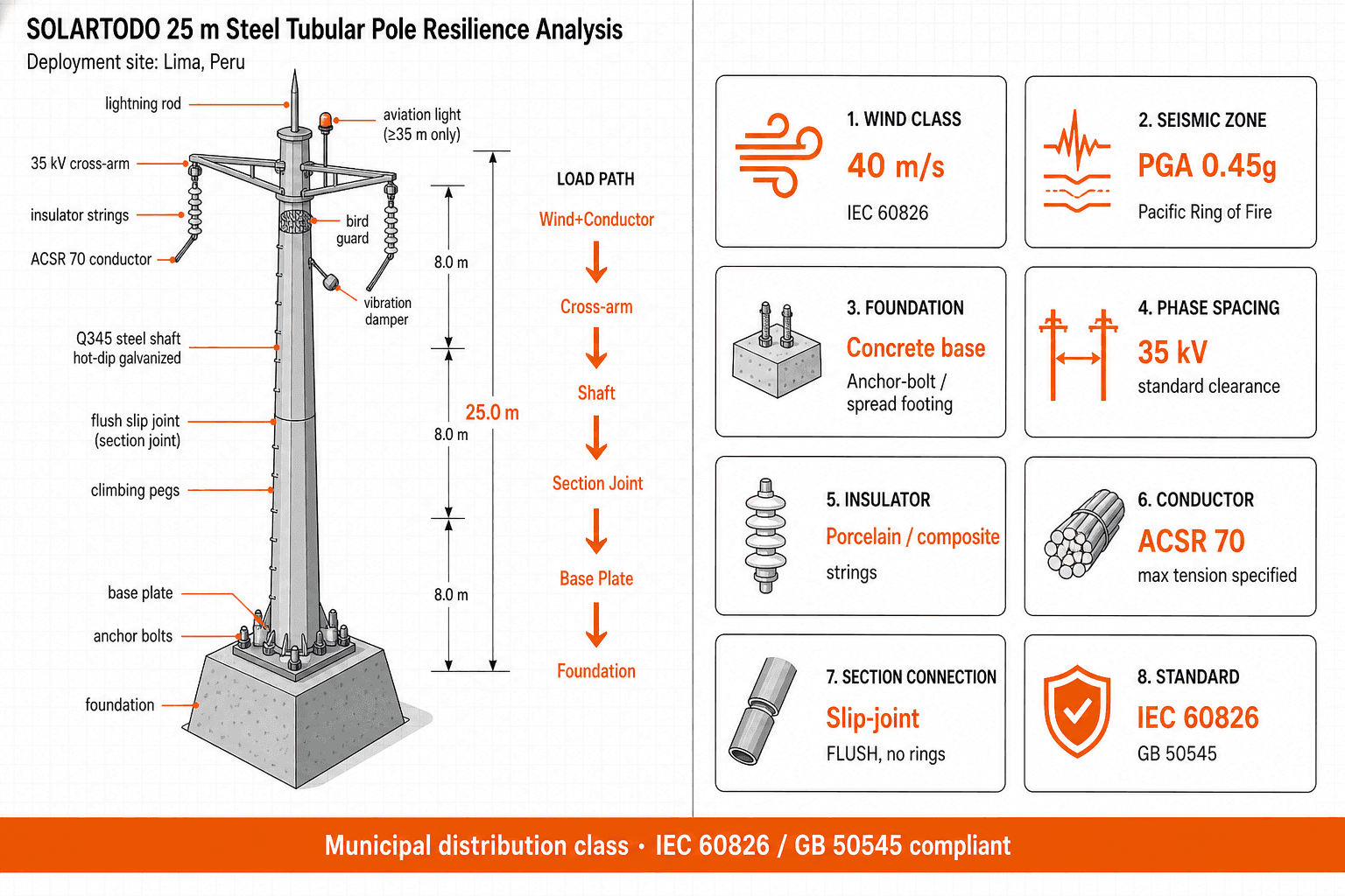
- Each tapered Q345 steel tubular pole is specified at 25m height, approximately 10t/pole, and 400kg/m structural mass.
- The electrical set uses ACSR-70 conductor rated around 275kg/km with maximum tension of 22kN.
- Phase spacing is 1.5m, minimum ground clearance is 5.5m, and insulator string length is 0.8m.
- Lima's coastal exposure supports hot-dip galvanizing, grounding, bird guards, vibration dampers, and 30-year design life.
- Wind Class 2 at 30m/s is appropriate for a medium-voltage municipal distribution profile in coastal Lima.
- The configuration should be checked against IEC 60826, GB 50545, and Peru's utility interconnection requirements before procurement.
Market Context for Lima
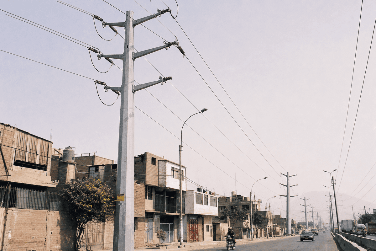
Lima is a 10-million-plus coastal megacity where distribution reinforcement must serve dense residential districts, port-linked logistics, and inland growth corridors.
According to INEI-linked 2023 population estimates, the Lima-Callao metropolitan area reaches about 11.3 million residents across Lima and Callao, making it Peru's largest load concentration. That scale creates steady demand for medium-voltage feeders serving Lima Norte, Lima Este, Lima Sur, Callao logistics zones, water pumping, commercial corridors, and municipal services. For a Power Transmission Tower specification, the relevant market is not bulk 500kV transmission across long rural spans, but compact municipal reinforcement where double-circuit overhead routes can increase feeder capacity without doubling right-of-way.
According to the World Bank (2023), Peru's electricity access indicator tracks the share of population with electricity access, and Peru's urban access is already high; Lima's challenge is therefore reinforcement, quality, and resilience rather than first-time electrification. World Bank states, 'Access to electricity is the percentage of population with access to electricity.' For Lima, that means EPC buyers often evaluate poles by outage reduction, corrosion durability, clearance, constructability, and permitting fit rather than by household connection count alone.
According to WMO climate summaries and SENAMHI-linked public climate data, Lima has a subtropical desert climate with very low rainfall but persistent coastal humidity and winter drizzle. The combination matters for steel structures: rain-driven wash-off is limited, salt-laden marine air can remain on surfaces, and grounding continuity must be maintained over a long service life. Hot-dip galvanized Q345 steel, closed tubular geometry, and specified accessories are therefore more suitable than untreated steel or wood for exposed municipal feeders.
According to COES and Peru power-sector planning materials, the national system uses high-voltage backbones such as 220kV and 500kV, while urban utilities distribute power through medium-voltage and sub-transmission networks closer to demand. A 35kV double-circuit line in Lima should be treated as a municipal distribution asset with utility review for feeder coordination, protection settings, and right-of-way clearances. SOLARTODO's role in this analysis is to map that infrastructure need to a buildable steel tubular pole configuration, not to claim a completed Lima project.
Recommended Technical Configuration
A Lima 35kV double-circuit corridor of approximately 18km would typically use 225 galvanized steel tubular monopoles at 80m spacing.
The recommended product form is a tapered round or dodecagonal steel monopole made from hot-dip galvanized Q345 steel, with flanged bolt sections and an anchor-bolt cage foundation. The specified line is 35kV double circuit, using cross-arm brackets for insulator strings and ACSR conductors. A typical N-unit deployment of this scale would be described as approximately 225 units, not as an installed project quantity.
The supplied design profile calls for 25m tapered steel tubular poles at approximately 10t/pole and 400kg/m. Because standard 10-35kV distribution corridors often use shorter 12-18m poles, this 25m recommendation should be interpreted as a constrained municipal profile for double-circuit routing, accessory loading, clearance management, and utility-specific urban geometry. Final acceptance should be confirmed by the Lima utility, civil designer, and project owner's grid study before manufacturing release.
The conductor recommendation is ACSR-70, with nominal mass around 275kg/km and maximum tension of 22kN. Phase spacing of 1.5m, insulator length of 0.8m, and minimum ground clearance of 5.5m are consistent with a compact medium-voltage municipal distribution route when verified against sag, temperature, wind, and safety factors. SOLARTODO should position this as a technical fit recommendation for procurement review, not as a historical deployment claim.
IEC states, 'Design criteria of overhead transmission lines,' which is the scope title of IEC 60826 and directly relevant to structural loading and reliability checks. GB 50545 provides a parallel design reference for overhead line engineering practice, while local Peruvian requirements should govern final route approval. For technical support or line-by-line configuration review, buyers can contact us with route length, wind data, soil report, and utility clearance requirements.
Technical Specifications
The recommended Lima configuration specifies approximately 225 units of 25m Q345 galvanized steel tubular poles for an 18km, 35kV double-circuit line.
- Product form: steel tubular Power Transmission Tower, not lattice, FRP, wood, or concrete.
- Voltage class: 35kV medium-voltage municipal distribution.
- Circuit configuration: double circuit with cross-arm brackets for insulator strings and ACSR conductors.
- Pole geometry: tapered round or dodecagonal steel monopole with flanged bolt sections.
- Steel grade and protection: hot-dip galvanized Q345 steel for coastal corrosion resistance.
- Quantity and route length: approximately 225 units over about 18km.
- Pole height and mass: 25m height, approximately 10t/pole, about 400kg/m.
- Conductor: ACSR-70, approximately 275kg/km, maximum tension 22kN.
- Electrical clearances: 1.5m phase spacing, 5.5m ground clearance, 0.8m insulator length.
- Span: 80m design span, aligned with compact municipal distribution routing.
- Wind class: Class 2, 30m/s design wind.
- Foundation: concrete anchor-bolt cage foundation with route-specific geotechnical sizing.
- Accessories: climbing steps, cross arm, grounding, bird guard, vibration damper.
- Design life: 30 years, subject to inspection, grounding checks, and corrosion monitoring.
- Standards basis: IEC 60826 and GB 50545, with Peru utility requirements applied during engineering review.
Implementation Approach
A 225-pole Lima distribution project would typically progress through 5 phases: survey, engineering approval, fabrication, foundation works, and commissioning.
The first phase should verify the corridor: alignment, road crossings, building setbacks, existing feeders, telecom conflicts, and soil parameters for every foundation group. In Lima, this step is especially important because dense districts, informal utility attachments, and coastal corrosion zones can change pole-top loading and grounding details. Survey output should include span tables, pole schedule, sag-tension assumptions, and grounding design.
The second phase is engineering and approval. The 35kV double-circuit design should be checked under normal, wind, broken-wire, erection, and maintenance load cases. According to IEC 60826 (2017), overhead line design uses reliability-based criteria for structural loading; that is why conductor tension, 30m/s wind, flanged joints, and anchor cage design should be treated as linked variables rather than separate purchase items.
The third phase is manufacturing and logistics. Tubular sections can be fabricated in modular flanged lengths, hot-dip galvanized, bundled with cross arms and accessories, and shipped CKD-style for efficient ocean freight. The buyer should specify marking, bolt packs, galvanizing certificates, mill certificates, conductor data sheets, and inspection hold points before shipment.
The fourth phase is civil installation. Anchor-bolt cages are set first, then concrete foundations cure before monopole erection begins. A typical field sequence includes excavation, cage alignment, concrete placement, grounding conductor installation, pole assembly, torque verification, cross-arm mounting, insulator installation, conductor stringing, vibration damper placement, and final clearance inspection.
The fifth phase is electrical commissioning. The EPC team should verify phase spacing, continuity, grounding resistance, insulator orientation, conductor sag, bird guard placement, and as-built GPS records. Final energization depends on utility switching procedures, protection coordination, and safety sign-off.
Expected Performance & ROI
The expected performance case is a 30-year municipal distribution asset with 18km of double-circuit capacity and reduced right-of-way pressure.
For a city like Lima, ROI should be modeled as avoided outage exposure, deferred underground cable cost, reduced feeder congestion, and lower replacement frequency rather than simple product resale value. A double-circuit overhead line can carry two feeders on one pole line, which is valuable when streets, industrial roads, or peri-urban corridors cannot accept two separate routes. The 80m span and 225-pole count also create predictable inspection intervals and spare-parts planning.
According to IEA (2023), electricity grids are becoming a central constraint in power-system expansion as electrification and demand growth accelerate. IEA states, 'Grids are the backbone of today's power systems.' In Lima, that principle applies at the distribution level: medium-voltage reinforcement enables new commercial loads, pumping stations, EV charging clusters, and industrial service upgrades without requiring every project to wait for high-voltage backbone expansion.
A practical payback model for a 35kV municipal feeder should include avoided outage penalties, avoided diesel backup, lower right-of-way acquisition cost versus duplicate feeder routes, and lower mid-life replacement risk from galvanized steel. Many utilities evaluate such investments over 20-30 years, with payback depending on outage cost, load growth, and whether the alternative is underground cable, concrete poles, or new routing. SOLARTODO should present the model as conditional, route-specific, and auditable.
Results and Impact
A technically matched Lima configuration would improve feeder resilience across 18km while keeping the pole form standardized for 30-year maintenance.
The main impact is infrastructure readiness rather than a claimed deployment result. With approximately 225 standardized steel tubular monopoles, the owner can simplify spares, inspection training, galvanizing documentation, and bolt-pack management. Accessories such as bird guards and vibration dampers reduce avoidable service events in coastal and urban-edge corridors.
The second impact is corridor efficiency. Double-circuit 35kV construction places two circuits on one structure line, reducing the need for parallel pole routes where land and permitting are constrained. For Lima's dense growth corridors, that can be the difference between a feasible overhead reinforcement and a delayed route negotiation.
The third impact is lifecycle control. A 30-year design life, hot-dip galvanizing, grounding provisions, and anchor-bolt cage foundations give EPC teams a maintainable asset with known inspection points. The result should be documented through factory QA records, foundation pour records, torque logs, sag-tension records, and commissioning checklists rather than promotional project claims.
Comparison Table
The table compares 4 pole options using voltage class, span, mass, and Lima-specific suitability criteria for medium-voltage planning.
| Option | Voltage class | Typical height | Typical weight | Span | Lima fit | Notes |
|---|---|---|---|---|---|---|
| Standard 10-35kV distribution pole | 10-35kV | 12-18m | 1-3t/pole | 80-150m | Moderate | Lower cost envelope, but less margin for constrained double-circuit urban clearances |
| Recommended Lima steel tubular configuration | 35kV | 25m | ~10t/pole | 80m | High | Approximately 225 units, double circuit, Q345 galvanized, ACSR-70, 30m/s wind |
| 66-110kV sub-transmission pole | 66-110kV | 18-30m | 5-15t/pole | 200-300m | Conditional | Appropriate only if utility upgrades the corridor to sub-transmission duty |
| 220kV HV transmission monopole | 220kV | 35-55m | 15-35t/pole | 350-450m | Low | Over-scaled for municipal 35kV distribution and typically requires larger right-of-way |
Pricing & Quotation
SOLARTODO offers three pricing tiers for this product line: FOB Supply (equipment ex-works China), CIF Delivered (including ocean freight and insurance), and EPC Turnkey (fully installed, commissioned, with 1-year warranty). Volume discounts are available for large-scale deployments. Configure your system online for an instant estimate, or request a custom quotation from our engineering team at [email protected].
No unit prices are included in this article because steel grade, galvanizing thickness, foundation design, freight route, conductor package, and EPC scope materially change the quotation. For Lima, a credible RFQ should include the 18km route plan, 225-pole schedule, wind requirement, soil report, accessory list, and utility approval checklist. SOLARTODO can then separate steel supply, logistics, and turnkey construction assumptions for procurement review.
Frequently Asked Questions
These 10 answers address Lima buyers' main 35kV questions: specification, installation, timeline, ROI, maintenance, pricing structure, warranty, and alternatives.
Q1: What is the recommended Power Transmission Tower configuration for Lima? The recommended configuration is approximately 225 units of 25m tapered steel tubular poles for an 18km, 35kV double-circuit municipal distribution line. Each pole uses hot-dip galvanized Q345 steel, flanged bolt sections, anchor-bolt cage foundations, 1.5m phase spacing, 5.5m ground clearance, ACSR-70 conductors, and accessories such as grounding, bird guards, and vibration dampers.
Q2: Is this a completed SOLARTODO project in Lima? No. This article is a market analysis and technical configuration guide, not a fabricated case study. The approximately 225-unit quantity, 18km route length, and 35kV double-circuit design are presented as a typical deployment profile for engineering and procurement review. They should not be read as a claim that SOLARTODO completed an installation in Lima.
Q3: Why use steel tubular monopoles instead of lattice towers? Steel tubular monopoles suit municipal corridors because they use a smaller ground footprint, cleaner visual profile, and standardized flanged sections. For Lima's dense roads and peri-urban growth areas, a tapered galvanized monopole can simplify right-of-way coordination compared with lattice structures. Lattice towers remain useful for larger transmission spans, but this 35kV profile is distribution-focused.
Q4: How long would deployment typically take? A typical schedule depends on permitting, foundation curing, utility outages, and shipping. For an 18km route, planning and engineering may take 4-8 weeks, fabrication and galvanizing 6-10 weeks, logistics 4-6 weeks, and field works several months depending on crews and access. Commissioning follows conductor stringing, grounding tests, clearance checks, and utility switching approval.
Q5: What maintenance is required over a 30-year design life? Maintenance should include annual visual inspection, post-storm checks, grounding resistance testing, bolt torque sampling, corrosion review, conductor sag observation, and accessory inspection. Coastal humidity in Lima makes galvanizing condition and grounding continuity especially important. Bird guards, vibration dampers, and insulator hardware should be checked at routine intervals and after abnormal wind or seismic events.
Q6: What is the expected ROI or payback period? ROI is conditional because poles do not generate revenue directly. Payback should be calculated from avoided outages, deferred underground cable cost, reduced right-of-way duplication, improved feeder capacity, and lower replacement frequency. For municipal distribution, owners often evaluate benefits over 20-30 years, with the strongest case where double-circuit overhead routing avoids expensive civil works.
Q7: Does SOLARTODO provide EPC pricing for Lima? SOLARTODO structures quotations as FOB Supply, CIF Delivered, or EPC Turnkey, but this guide intentionally excludes prices. EPC pricing depends on soil, access roads, foundation volume, crane availability, outages, conductor package, and local labor scope. Buyers should submit route drawings, pole schedule, wind class, foundation assumptions, and utility requirements for a defensible quotation.
Q8: What standards apply to the 35kV pole design? The stated design references are IEC 60826 and GB 50545, with local Peruvian utility requirements applied during approval. IEC 60826 supports structural loading and reliability checks for overhead lines, while GB 50545 provides overhead line design guidance. Final engineering should verify sag, wind, clearances, foundations, grounding, and protection coordination for the actual Lima corridor.
Q9: What warranty structure is typical for this product line? For the EPC Turnkey tier, the required SOLARTODO paragraph specifies a 1-year warranty. Supply-only warranty terms should be confirmed in the purchase contract and tied to steel grade, galvanizing, fabrication tolerances, and accessory specifications. Long-term performance still depends on correct foundation installation, grounding, inspections, and avoiding unauthorized attachments that change loading.
Q10: Can the configuration use larger ACSR conductors later? Possible conductor upgrades must be checked structurally and electrically before approval. ACSR-120, ACSR-240, or ACSR-400 would increase conductor weight, wind area, tension, and pole-top load. The current recommendation is ACSR-70 at about 275kg/km and 22kN maximum tension, so larger conductors require revised sag-tension, cross-arm, foundation, and clearance calculations.
References
The 7 references below support Lima's population context, climate exposure, Peru grid planning, and 35kV overhead-line engineering assumptions.
- INEI (2023): Lima-Callao metropolitan population estimates around 11.3 million residents; source portal: https://www.inei.gob.pe/
- World Bank (2023): Access to electricity indicator for Peru and electricity-sector development context; source: https://data.worldbank.org/indicator/EG.ELC.ACCS.ZS?locations=PE
- COES (2024): Peru SEIN operation and transmission planning context, including high-voltage system coordination; source: https://www.coes.org.pe/
- SENAMHI / WMO (2024): Lima coastal desert climate, high humidity, low rainfall, and meteorological context; source: https://www.gob.pe/senamhi and https://worldweather.wmo.int/
- IEC (2017): IEC 60826, Design criteria of overhead transmission lines; source: https://webstore.iec.ch/
- GB 50545 (2010): Code for design of 110kV-750kV overhead transmission lines, used as an engineering reference for Chinese steel pole design practice.
- MINEM Peru (2011): Codigo Nacional de Electricidad - Suministro, national electrical supply requirements for line safety and clearances; source: https://www.gob.pe/minem
Equipment Deployed
- 225 units x 25m tapered Q345 hot-dip galvanized steel tubular monopole
- 35kV double-circuit medium-voltage municipal distribution configuration
- ACSR-70 conductor, 275kg/km, maximum tension 22kN
- 80m design span over approximately 18km route length
- 1.5m phase spacing, 5.5m ground clearance, 0.8m insulator length
- Wind Class 2 design at 30m/s
- Concrete anchor-bolt cage foundation
- Accessories: climbing steps, cross arm, grounding, bird guard, vibration damper
- 30-year design life with IEC 60826 / GB 50545 standards basis